Removal
INSPECTION
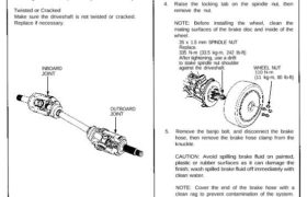
Driveshaft Boot
Check the boots on the driveshaft for cracks, damage,
leaking grease and loose boot bands.
If any damage is found, replace the boot.
Spline Looseness
Turn the driveshaft by hand, and make sure the splines
and joints are not excessively loose.
If damage is found, replace the joints if necessary.
Twisted or Cracked
Make sure the driveshaft is not twisted or cracked.
Replace if necessary.
INBOARD
JOINT
OUTBOARD
JOINT
1. Raise the car, and place safety stands in the proper
locations (see section 1).
2. Remove the rear wheels.
3. Drain the transmission oil or fluid (see section 13
M/T or section 14 A/T).
NOTE: It is not necessary to drain the transmission
oil when the right driveshaft is removed.
4. Raise the locking tab on the spindle nut, then
remove the nut.
NOTE: Before installing the wheel, clean the
mating surfaces of the brake disc and inside of the
wheel.
26 x 1.5 mm SPINDLE NUT
Replace.
335 N-m (33.5 kg-m, 242 Ib-ft)
After tightening, use a drift
to stake spindle nut shoulder
against the driveshaft. WHEEL NUT
110 N-m
(11 kg-m, 80 Ib-ft)
5. Remove the banjo bolt, and disconnect the brake
hose, then remove the brake hose clamp from the
knuckle.
CAUTION: Avoid spilling brake fluid on painted,
plastic or rubber surfaces as it can damage the
finish; wash spilled brake fluid off immediately with
clean water.
NOTE: Cover the end of the brake hose with a
clean rag to prevent contamination of the system.
Then secure the hose to the suspension arm.
BANJO BOLT
35 N-m
(3.5 kg-m, 25 Ib-ft)
BRAKE HOSE
WASHER
Replace.
Corrosion resistant bolt
6 mm BOLT
10 N-m
(1.0 kg-m, 7 Ib-ft)
Driveshafts
Removal
6. Remove the wheel sensor from the knuckle and the
rear of the lower arm, then secure the wheel sensor
wire to the suspension arm.
NOTE:
• Do not disconnect the wheel sensor.
• Avoid twisting the wires when reinstalling the
wheel sensor.
7. Disconnect the parking brake cable from the body.
Corrosion resistant bolt
8 mm FLANGE BOLTS
22 N-m (2.2 kg-m, 16 Ib-ft) PARKING BRAKE CABLE
WHEEL SENSOR 6 mm BOLT-WASHER
10 N-m (1.0 kg-m, 7 Ib-ft)
8 mm BOLT-WASHER
22 N-m (2.2 kg-m, 16 Ib-ft)
Corrosion resistant bolt
TOE CONTROL ARM FLANGE BOLT
12 x 1.25 mm
95 N-m (9.5 kg-m, 69 Ib-ft)
9. Hold the damper lower mount of stabilizer link with
a wrench, and remove the damper mounting nut.
10. Hold the ball pin of the stabilizer link with a hex
wrench, and loosen the self-locking nut.
Corrosion resistant nut
DAMPER MOUNTING NUT
12 x 1.25 mm
Replace.
95 N-m (9.5 kg-m, 69 Ib-ft)
WRENCH
HEX WRENCH
STABILIZER LINK
SELF-LOCKING NUT
12 x 1.25 mm
Replace.
85 N-m (8.5 kg-m, 61 Ib-ft)
11. Remove the self-locking nut, then remove the
stabilizer link from the stabilizer bar and knuckle.
Corrosion resistant nut
REAR DAMPER
SELF-LOCKING NUT
12 x 1.25 mm
Replace.
STABILIZER LINK
8. Remove the flange bolt, then disconnect the toe
control arm from the body.
12. Remove the self-locking nut and flange bolt.
13. Remove the self-locking nut and adjusting bolt,
then disconnect the lower control arm from the
sub-frame.
Corrosion resistant bolt/nut
LOWER CONTROL ARM
14 x 1.5 mm
Replace.
125 N-m (12.5 kg-m, 90 Ib-ft)
ADJUSTING CAM
ADJUSTING BOLT
FLANGE BOLT
SELF-LOCKING NUT
14 x 1.5 mm
Replace.
125 N-m (12.5 kg-m, 90 Ib-ft)
14. Pull the knuckle outward, and remove the driveshaft
outboard joint from the knuckle using a plastic
hammer.
KNUCKLE
OUTBOARD JOINT
15. Pry the driveshaft assembly with a screwdriver as
shown to force the set ring past the groove.
SCREWDRIVER
3.5 mm
7 mm
16. Pry the inboard joint outward, then remove the
driveshaft and CV joint from of the differential case
or intermediate shaft as an assembly.
CAUTION:
• Do not pull on the driveshaft, as the CV joint
may come apart.
• Use care when prying out the assembly, and pull
it straight to avoid damaging the differential oil
seal or intermediate shaft dust seal.
INBOARD JOINT
17. Installation is the reverse order of removal.
After installing the driveshafts, adjust the wheel
alignment (see section 18).