Clutch Pedal
Adjustment
NOTE:
• To check the switch, see section 23.
• The clutch is self-adjusting to compensate for wear.
CAUTION: If there is no clearance between the
master cylinder piston and push rod, the release
bearing is held against the diaphragm spring, which
can result in clutch slippage or other clutch
problems.
1. Loosen locknut A, and back off the pedal switch
until it no longer touches the clutch pedal.
2. Loosen locknut C, and turn the push rod in or out to
get the specified stroke and height at the clutch
pedal.
3. Tighten locknut C.
4. Thread in the clutch pedal switch A in until it con-
tacts the clutch pedal.
5. Turn the switch in 1/4 — 1/2 turn further.
6. Tighten locknut A.
7. Loosen locknut B and pedal switch B.
8. Measure the clearance between the floor board and
clutch pedal with the clutch pedal fully depressed.
9. Release the clutch pedal 15-20 mm (0.59-0.79
in) from the fully depressed position, and hold it
there. Adjust the position of pedal switch B so that
the engine will start with the clutch pedal in this
position.
10. Thread in pedal switch B in 1/4 — 1/2 turn further.
11. Tighten locknut B.
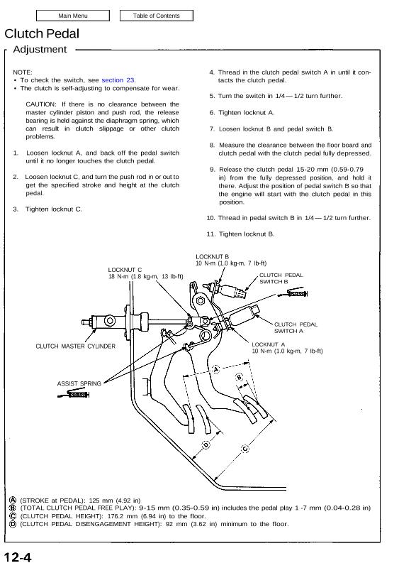
LOCKNUT C
18 N-m (1.8 kg-m, 13 Ib-ft)
LOCKNUT B
10 N-m (1.0 kg-m, 7 Ib-ft)
CLUTCH PEDAL
SWITCH B
ASSIST SPRING
CLUTCH PEDAL
SWITCH A
LOCKNUT A
10 N-m (1.0 kg-m, 7 Ib-ft)
(STROKE at PEDAL): 125 mm (4.92 in)
(TOTAL CLUTCH PEDAL FREE PLAY): 9-15 mm (0.35-0.59 in) includes the pedal play 1 -7 mm (0.04-0.28 in)
(CLUTCH PEDAL HEIGHT): 176.2 mm (6.94 in) to the floor.
(CLUTCH PEDAL DISENGAGEMENT HEIGHT): 92 mm (3.62 in) minimum to the floor.
CLUTCH MASTER CYLINDER
Adjustment
NOTE:
• To check the switch, see section 23.
• The clutch is self-adjusting to compensate for wear.
CAUTION: If there is no clearance between the
master cylinder piston and push rod, the release
bearing is held against the diaphragm spring, which
can result in clutch slippage or other clutch
problems.
1. Loosen locknut A, and back off the pedal switch
until it no longer touches the clutch pedal.
2. Loosen locknut C, and turn the push rod in or out to
get the specified stroke and height at the clutch
pedal.
3. Tighten locknut C.
4. Thread in the clutch pedal switch A in until it con-
tacts the clutch pedal.
5. Turn the switch in 1/4 — 1/2 turn further.
6. Tighten locknut A.
7. Loosen locknut B and pedal switch B.
8. Measure the clearance between the floor board and
clutch pedal with the clutch pedal fully depressed.
9. Release the clutch pedal 15-20 mm (0.59-0.79
in) from the fully depressed position, and hold it
there. Adjust the position of pedal switch B so that
the engine will start with the clutch pedal in this
position.
10. Thread in pedal switch B in 1/4 — 1/2 turn further.
11. Tighten locknut B.
LOCKNUT C
18 N-m (1.8 kg-m, 13 Ib-ft)
LOCKNUT B
10 N-m (1.0 kg-m, 7 Ib-ft)
CLUTCH PEDAL
SWITCH B
ASSIST SPRING
CLUTCH PEDAL
SWITCH A
LOCKNUT A
10 N-m (1.0 kg-m, 7 Ib-ft)
(STROKE at PEDAL): 125 mm (4.92 in)
(TOTAL CLUTCH PEDAL FREE PLAY): 9-15 mm (0.35-0.59 in) includes the pedal play 1 -7 mm (0.04-0.28 in)
(CLUTCH PEDAL HEIGHT): 176.2 mm (6.94 in) to the floor.
(CLUTCH PEDAL DISENGAGEMENT HEIGHT): 92 mm (3.62 in) minimum to the floor.
CLUTCH MASTER CYLINDER