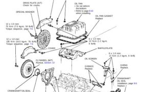
Illustrated Index
Lubricate all internal parts with engine oil during reassembly.
NOTE:
• Apply liquid gasket to the mating surfaces of the
left side cover and oil pump case before install-
ing them.
• Use liquid gasket, part No. 08718-0001.
If the bottom of the oil pan is deformed, it should
be repaired or the oil pan should be replaced re-
tain proper clearance between the screen and
the bottom.
COVER
DRIVE PLATE (A/T)
Check for cracks.
SPECIAL WASHER
12 x 1.0 mm
75 N-m (7.5 kg-m, 54 Ib-ft)
Torque sequence, page 7-6
12 x 1.0 mm
105 N-m (10.5 kg-m. 76 Ib-ft)
Torque sequence, page 7-6
6 x 1.0 mm
14 N-m (1.4 kg-m, 10 Ib-ft)
OIL PAN
• Do not deform
the bottom.
• Refer to page 8-10
when installing.
OIL PAN GASKET
Replace
6 x 1.0 mm
12 N-m (1.2 kg-m, 9 Ib-ft)
O-RING
Replace.
CRANKSHAFT
OIL SEAL
Installation, page 8-9
Replace.
CRANKSHAFT OIL SEAL
Installation, page 7-18
Replace.
SPECIAL BOLT
6 x 1.0 mm
12 N-m (1.2 kg-m,
9 Ib-ft)
Replace.
OIL PASS
PIPE/JOINT
LEFT
SIDE COVER
Apply liquid gasket
to mating surface.
DOWEL PINS
OIL PUMP
Overhaul, page 8-7
Removal/Inspection,
page 8-8
Apply liquid gasket
to mating surface.
SPECIAL BOLTS
8 x 1.25 mm
22 N-m (2.2 kg-n
16 Ib-ft)
Replace.
SPECIAL BOLTS
6 x 1.0 mm
12 N-m (1.2 kg-m, 9 Ib-ft)
Replace.
DOWEL PINS
O-RINGS
Replace.
OIL SCREEN
FLYWHEEL (M/T)
Runout, section 12
BAFFLE PLATE
6 x 1.0 mm
12 N-m (1.2 kg-m,
9 Ib-ft)
COVER
Engine Block
Illustrated Index
Lubricate all internal parts with engine oil during reassembly.
MAIN BEARING
CAP BRIDGE
10 x 1.25 mm
50 N-m (5.0 kg-m, 36 Ib-ft)
Apply engine oil to the
bolt threads and the washers.
MAIN BEARING
CAP
CRANKSHAFT
End play, page 7-6
Runout, Taper, and
Out-of-Round, page 7-11
Installation, page 7-18 to 7-21
THRUST WASHERS
Replacement, page 7-6
Grooved sides face outward.
NOTE: Thrust washer thickness
is fixed and must not be changed
by grinding or shimming.
11 x 1.5 mm
66 N-m
(6.6 kg-m, 48 Ib-ft)
Apply engine oil to the bolt
threads and the washers.
NOTE: After torquing
each cap, turn crankshaft
to check for binding.
9 x 1.25 mm
40 N-m (4.0 kg-m, 29 Ib-ft)
Apply engine oil to the
bolt threads
DOWEL PIN
MAIN BEARINGS
Radial clearance, page 7-7
Selection, page 7-8
NOTE: New main bearings
must be selected by matching
crank and block identification
markings.
6 x 1.0 mm
12 N-m (1.2 kg-m,
9 Ib-ft)
DOWEL PIN
OIL BREATHING
COVER
O-RING
Replace.
NOTE: New rod bearings must be selected by matching
connecting rod assembly and crankshaft identification
markings (see page 7-8).
TIMING
BELT
SIDE
CAUTION:
• The piston skirt is coated with molybdenum;
handle the piston carefully to prevent any
damage.
• The connecting rods are made of titanium. At-
tempting to remove the piston pin with conven-
tional shop equipment will damage the connec-
ting rod.
• If the piston, connecting rod, or piston pin re-
quire replacement, all three must be replaced as
an assembly.
PISTON
Inspection, page 7-13
NOTE:
• Before removing piston, inspect the top
of the cylinder bore for carbon build-up
or ridge. Remove ridge if necessary, page 7-9.
• To maintain proper piston clearance, match
the letter on the piston top (No letter denotes A.)
with the letter for each cylinder stamped on the
block.
CONNECTING ROD ASSEMBLY
End play, page 7-6
Selection, page 7-14
CONNECTING ROD
BEARINGS
Clearance, page 7-7
Selection, page 7-8
CONNECTING ROD
WASHER
CONNECTING ROD CAP NUT
8 x 0.75 mm
20 N-m (2.0 kg-m, 14 Ib-ft)
then turn 95°
After torquing each bearing
cap, rotate crankshaft to
check for binding.
CYLINDER BORE SIZES
NOTE: To maintain proper piston clearance,
match these letters with the letters on the
pistons. The letters on the block read from
left to right, No. 1 through No. 3. cylinders
on the first line and No. 4 through No. 6
cylinders on the second line.
CONNECTING ROD BEARING CAP
Installation, page 7-18 to 7-21
NOTE: Install caps so the bearing recess is
on the same side as the recess in the rod.
PISTON RINGS
Replacement, page 7-15
Measurement, pages 7-15 and 7-16
Alignment, page 7-16
CONNECTING ROD BOLT
Inspect top of each cylinder bore
for carbon build-up or ridge
before removing piston.
Remove ridge if necessary, page 7-9
ENGINE BLOCK
Cylinder bore inspection, page 7-12
Warpage inspection, page 7-12
Cylinder bore honing, page 7-13