Category: Steering
Categories
nsxb17009a.pdf
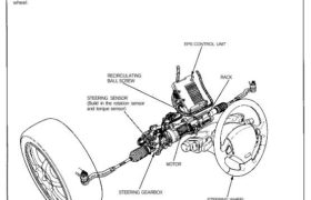
System Operation Manual Steering Operation Steering wheel input rotates the pinion of the gearbox through a universal joint. Due to the rack and pinion mechanism, the rotation of pinion is converted into a transverse motion at the rack, which steers the front wheels throught the tie-rods and knuckles the same as an ordinary rack and […]
Categories
nsxd17032a.pdf
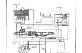
FUSE BOX System Description Major Components The Electrical Power Steering system is composed of the following major components: EPS CONTROL UNIT COUNTERSHAFT SPEED SENSORALTERNATOR SPEEDOMETER EPS INDICATOR LIGHT STEERING SENSOR BATTERY POWER UNIT MOTOR IGNITION SWITCH A steering gearbox that converts rotary operation of the steering wheel into transverse operation via a rack and pinion […]
Categories
nsxb17023a.pdf
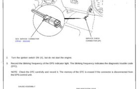
Diagnostic Trouble Code (DTC) Indication 1. Connect the SCS service connector to the service check connector under the glove box. SCS SERVICE CONNECTOR 07PAZ – 0010100 SERVICE CHECK CONNECTOR (2P) 2. Turn the ignition switch ON (II), but do not start the engine. 3. Record the blinking frequency of the EPS indicator light. The blinking […]
Categories
nsxb17004a.pdf
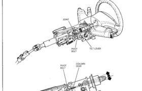
System Description Steering Column The NSX/NSX-T has a till/telescopic steering column. The tilt/telescopic mechanism makes it possible to adjust the steer- ing wheel in fore and aft, and up and down directions. Tilt Mechanism In the upper portion of the steering column is a joint on the steering shaft. This joint allows the steering wheel […]
Categories
nsxd17051a.pdf
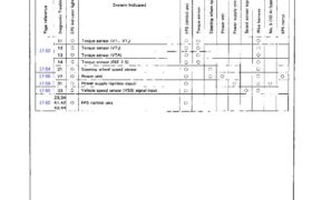
Troubleshooting Chart The EPS has been reported on: Connect the service check connector with a jumper wire (see page 17-43). Turn on the ignition switch. Read the Diagnostic Trouble Code (DTC) and perform the troubleshooting according to the troubleshooting chart below. 17-52 17-54 17-56 17-59 17-60 17-62 Attachments nsxd17051a (87 kB)
Categories
nsxd17063a.pdf
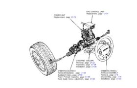
Component Location Index NOTE: EPS CONTROL UNIT Replacement, page 17-74 POWER UNIT Replacement, page 17-73 STEERING WHEEL/ AIRBAG ASSEMBLY Removal, page 17-8 Disassembly, page 17-9 Installation, page 17-10 STEERING COLUMN Removal, page 17-12 Inspection, page 17-14 Installation, page 17-15 STEERING GEARBOX Removal/Installation, page 17-64 Illustrated Index, page 17-68 Pinion Preload Inspection, page 17-69 Rack Guide […]
Categories
nsxb17016a.pdf
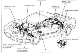
Component Locations GAUGE ASSEMBLY UNDER-HOOD FUSE/ RELAY BOX TRANSMISSION CONTROL MODULE (TCM) 22P CONNECTOR VEHICLE SPEED SENSOR (VSS) (M/T) PULSE UNIT 7P CONNECTOR TORQUE SENSOR 6P CONNECTOR/ ROTATION SENSOR 4P CONNECTOR STEERING GEARBOX (TORQUE SENSOR/ ROTATION SENSOR) UNDER-DASH FUSE BOX EPS CONTROL UNIT ALTERNATOR 4P CONNECTOR GAUGE ASSEMBLY EPS INDICATOR LIGHT UNDER-HOOD FUSE/RELAY BOX No. […]
Categories
nsxd17012a.pdf
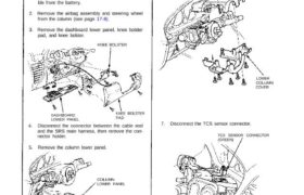
Steering Column Removal CAUTION: All SRS electrical wiring harnesses are covered with yellow outer insulation. Before disconnecting any part of the SRS wire harness, install the short connectors (see pages 24-10(’93-’96),23-323(’91-’92) and 24-11(’93-’96), 23-323(’91-’92). Replace the entire effected SRS harness assembly if it has an open circuit or damaged wiring. 1. Disconnect both the negative […]
Categories
nsxb17060a.pdf
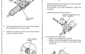
Steering Gearbox Inspection 1. Carefully clamp the gearbox in a vise with soft jaws. 2. Remove the boot bands. BOOT BAND Replace. 3. Pull the boots away from the ends of the gearbox, then unbend the tie-rod lock washers. 4. Hold the rack with a wrench, and unscrew the tie- rods with another wrench. LOCK […]
Categories
nsxd17015a.pdf
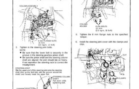
Installation CAUTION: All SRS wiring harnesses are covered with yellow outer insulation. Replace the entire affected SRS harness assembly if it has an open circuit or damaged wiring. 1. Slip the lower end of the steering joint onto the pin- ion shaft. 2. Reposition the column assembly on the hanger bracket and loosely tighten with […]