Category: Fuel & Emissions
nsxe11117a.pdf
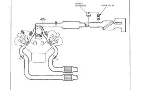
Dashpot System Description The dashpot is employed to slow the closing of the throttle valve during gear shifting or deceleration. DASHPOT DIAPHRAGM CHECK VALVE Attachments nsxe11117a (86 kB)
nsxd11133a.pdf
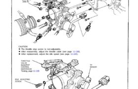
Throttle Body (cont’d) Disassembly THROTTLE CABLE 22 N·m (2.2 kg-m, 16lb-ft) CAUTION: THROTTLE VALVE DASHPOT TP SENSORCONTROL DIAPHRAGM Testing, page 11-135 IDLE ADJUSTING SCREW O-RING Replace The throttle stop screw is non-adjustable. After reassembly, adjust the throttle cable (see page 11-130). After replacement, adjust the idle speed (see page 11-102). Attachments nsxd11133a (196 kB)
nsxd11119a.pdf
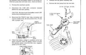
Testing Do not smoke during the test. Keep open If you suspect a problem with the fuel pump, check that the fuel pump actually runs; When it is ON, you will hear some noise if you hold your ear to the fuel fill port with the fuel fill cap removed. The fuel pump should run […]
nsxb11002a.pdf
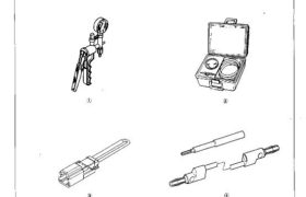
Special Tools 11-151,11-155, 11-163, 11-164, 11-168, 11-169, 11-170, 11-171, 11-173 11-173 11-38 11-40 11-133, 11-137 Mam Menu Table of Contents Special Tools Ref. No. 4 Tool Number Description ‘ Qty i Page Reference ‘10 A973X — 041 — XXXXX Vacuum Pump/Gauge 1 11-151,11-155,11-163, 11-164,11-168,11-169` 11-170, 11-171, 11-173 ® 07JAZ — OO‘IOOOB Vacuum/Pressure Gauge 0 v […]
nsxb11141a.pdf
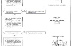
Fuel Pump Resistor Troubleshooting Flowchart — Engine will not start. — Inspection of fuel pump resis- tor. Check the operation of the PGM- FI main relay: 1. Disconnect the fuel pump resistor 2P connector. 2. Measure voltage between fuel pump resistor connector ter- minal No. 2 and body ground when the ignition switch is first […]
nsxb11010a.pdf
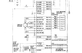
System Descriptions Electrical Connections Main Menu Table of Contents System Descriptions Electrical Connections IGNITION PGM-FI MAIN RELAY FUEL PUMP RESISTOR SWITCH CKPI CYP SENSOR INJECTORS BS CVP 1P B14 CYP 1M B7 CKP ZP B15 CKP 2M 88 CKP 1F B16 CKP 1M 85 CYP 2P B13 CYP 2M INJ1 A1 ⇀↼↴∣↸⇃↲⋜ A2 INJ3 A3 […]
nsxe11016a.pdf
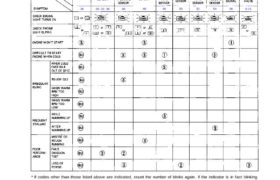
Troubleshooting Troubleshooting Guide NOTE: Across each row in the chart, the systems that could be sources of a symptom are ranked in the order they should be inspected starting with . Find the symptom in the left column, read across to the most likely source, then refer to the page listed at the top of […]
nsxe11108a.pdf
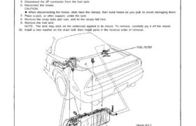
Fuel Supply System Fuel Tank Replacement Do not smoke while working on fuel system. Keep open flame away from work area. Make sure lifts are placed properly. (See page 1-6.) 1. Raise the car. 2. Remove the drain bolt and drain the fuel into an approved container. 3. Remove the center rod (Section 5). 4. […]
nsxb11158a.pdf
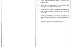
Emission Control System System Description The emission control system includes two Three Way Catalytic Converters (TWCs), Exhaust Gas Recirculation (EGR) system, Positive Crankcase Ventilation (PCV) sys- tem and Evaporative Emission (EVAP) Control system. The emission control system is designed to meet federal and state emission standards. Tailpipe Emission Inspection Do not smoke during this procedure. […]
nsxb11061a.pdf
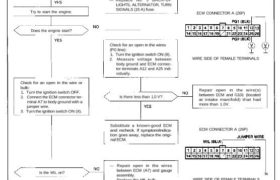
Engine Control Module (ECM) NOTE: If this symptom is intermittent, check for a loose No. 5 BACK-UP LIGHTS, ALTERNATOR, TURN SIGNALS (15 A) fuse in the under-dash fuse/relay box, a poor connection at ECM terminal A7, or an intermittent open in the BLU wire between the ECM (A7) and the gauge assembly. Is the low […]