Category: Fuel & Emissions
Categories
nsxb11003a.pdf
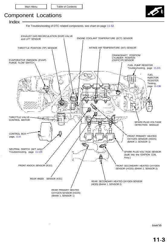
Component Locations Index EXHAUST GAS RECIRCULATION (EGR) VALVE and LIFT SENSOR THROTTLE POSITION (TP) SENSOR EVAPORATIVE EMISSION (EVAP) PURGE FLOW SWITCH ENGINE COOLANT TEMPERATURE (ECT) SENSOR INTAKE AIR TEMPERATURE (IAT) SENSOR CRANKSHAFT POSITION/ CYLINDER POSITION (CKP/CYP) SENSOR FUEL PUMP RESISTER Troubleshooting, page 11-141 FUEL INJECTOR RESISTER Testing, page 11-136 THROTTLE VALVE CONTROL MOTOR CONTROL BOX […]
Categories
nsxd11028a.pdf
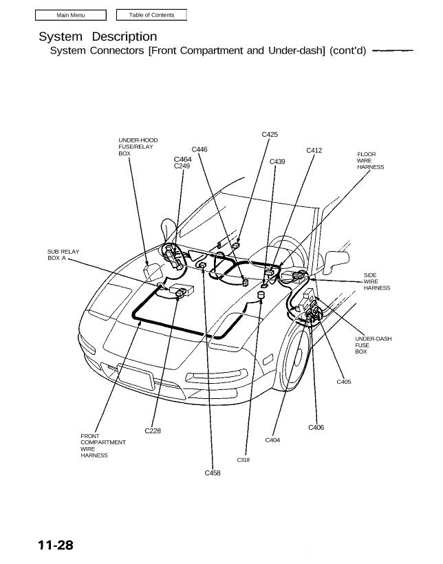
System Description System Connectors [Front Compartment and Under-dash] (cont’d) UNDER-HOOD FUSE/RELAY BOX C464 C249 C446 C425 C439 C412 FLOOR WIRE HARNESS SIDE WIRE HARNESS UNDER-DASH FUSE BOX C405 C406 C404 C318 C458 C228 FRONT COMPARTMENT WIRE HARNESS SUB RELAY BOX A C228 C318 C404 C405 C406 C412 C425 (A/T) C439 C446 C458 C464 NOTE: Several […]
Categories
nsxd11112a.pdf
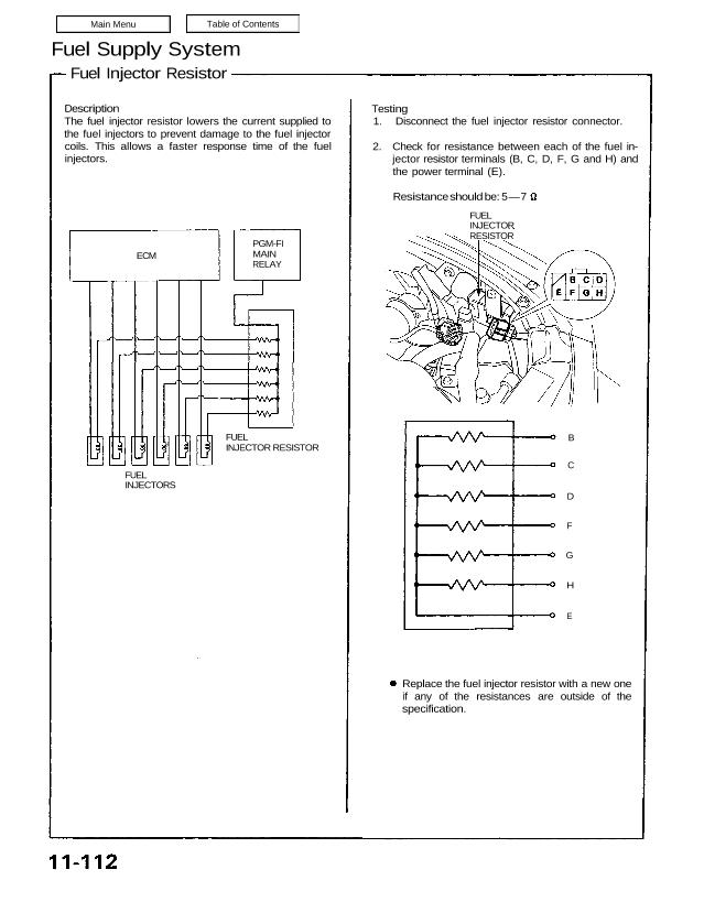
Fuel Supply System Fuel Injector Resistor Description The fuel injector resistor lowers the current supplied to the fuel injectors to prevent damage to the fuel injector coils. This allows a faster response time of the fuel injectors. ECM PGM-FI MAIN RELAY Testing 1. Disconnect the fuel injector resistor connector. 2. Check for resistance between each […]
Categories
nsxe11118a.pdf
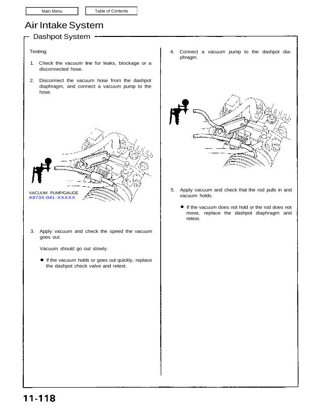
Air Intake System Dashpot System Testing 1. Check the vacuum line for leaks, blockage or a disconnected hose. 2. Disconnect the vacuum hose from the dashpot diaphragm, and connect a vacuum pump to the hose. 4. Connect a vacuum pump to the dashpot dia- phragm. VACUUM PUMP/GAUGE A973X-041 -XXXXX 5. Apply vacuum and check that […]
Categories
nsxb11034a.pdf
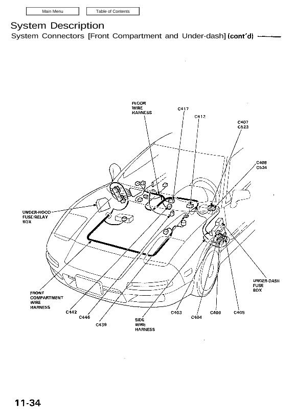
System Description System Connectors [Front Compartment and Under-dash] Mam Menu Table of Contents System Description System Connectors [Front Compartment and Under-dash](cont’d) FLOOR WIRE c41 7 HARNESS UNDER-HOOD FUSE/RELAY BOX V/ —.—-— UNDER-DASH ⇘ FUSE Ą” BOX FRONT . COMPARTMENT WIRE HARNESS C442 C446 C404 SIDE C439 WIRE HARNESS 11-34 NOTE: • Different wires with the […]
Categories
nsxd11124a.pdf
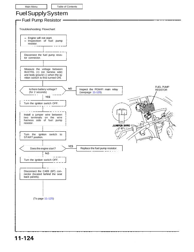
Fuel Supply System Fuel Pump Resistor Troubleshooting Flowchart (To page 11-125) FUEL PUMP RESISTORInspect the PGM-FI main relay (seepage 11-120). Engine will not start. Inspection of fuel pump resistor. Disconnect the fuel pump resis- tor connector. Measure the voltage between BLK/YEL (+) (on harness side) and body ground (-) when the ig- nition switch is […]
Categories
nsxd11006a.pdf
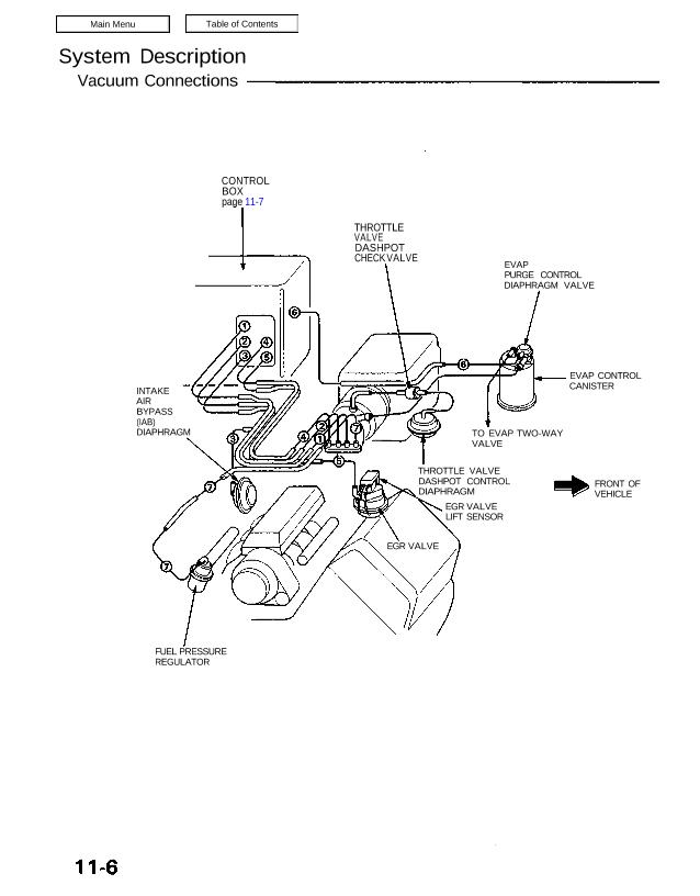
System Description Vacuum Connections CONTROL BOX page 11-7 THROTTLE VALVE DASHPOT CHECK VALVE EVAP PURGE CONTROL DIAPHRAGM VALVE EVAP CONTROL CANISTER TO EVAP TWO-WAY VALVE FRONT OF VEHICLE THROTTLE VALVE DASHPOT CONTROL DIAPHRAGM EGR VALVE LIFT SENSOR FUEL PRESSURE REGULATOR INTAKE AIR BYPASS (IAB) DIAPHRAGM EGR VALVE Control Box EVAPORATIVE EMISSION (EVAP) PURGE CONTROL SOLENOID […]
Categories
nsxb11126a.pdf
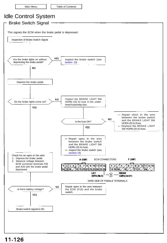
Idle Control System Brake Switch Signal This signals the ECM when the brake pedal is depressed. Are the brake lights on without depressing the brake pedal? Inspect the brake switch (see section 19). Depress the brake pedal. Do the brake lights come on? Is the fuse OK? Check for an open in the wire: 1. […]
Categories
nsxd11042a.pdf
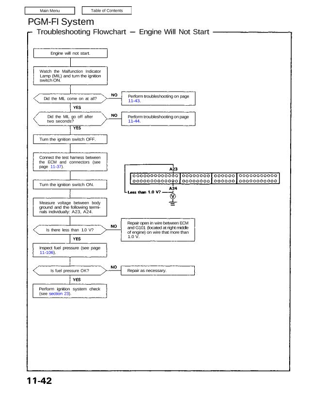
PGM-FI System Troubleshooting Flowchart Engine Will Not Start Engine will not start. Watch the Malfunction Indicator Lamp (MIL) and turn the ignition switch ON. Did the MIL come on at all? Did the MIL go off after two seconds? Turn the ignition switch OFF. Connect the test harness between the ECM and connectors (see page […]
Categories
nsxe11023a.pdf
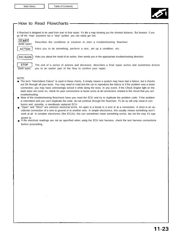
How to Read Flowcharts A flowchart is designed to be used from start to final repair. It’s like a map showing you the shortest distance. But beware: if you go off the “map” anywhere but a “stop” symbol, you can easily get lost. Describes the conditions or situation to start a troubleshooting flowchart. (bold type) […]