Flywheel and Drive Plate
Replacement
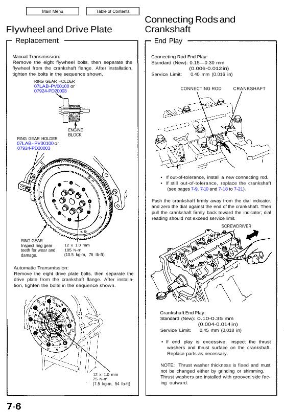
Manual Transmission:
Remove the eight flywheel bolts, then separate the
flywheel from the crankshaft flange. After installation,
tighten the bolts in the sequence shown.
RING GEAR HOLDER
07LAB -PV00100 or
07924-PD20003
RING GEAR HOLDER
07LAB – PV00100 or
07924-PD20003
ENGINE
BLOCK
RING GEAR
Inspect ring gear
teeth for wear and
damage.
12 x 1.0 mm
105 N-m
(10.5 kg-m, 76 Ib-ft)
Automatic Transmission:
Remove the eight drive plate bolts, then separate the
drive plate from the crankshaft flange. After installa-
tion, tighten the bolts in the sequence shown.
12 x 1.0 mm
75 N-m
(7.5 kg-m, 54 Ib-ft)
Connecting Rods and
Crankshaft
End Play
Connecting Rod End Play:
Standard (New): 0.15—0.30 mm
(0.006-0.012 in)
Service Limit: 0.40 mm (0.016 in)
CONNECTING ROD CRANKSHAFT
• If out-of-tolerance, install a new connecting rod.
• If still out-of-tolerance, replace the crankshaft
(see pages 7-9, 7-10 and 7-18 to 7-21).
Push the crankshaft firmly away from the dial indicator,
and zero the dial against the end of the crankshaft. Then
pull the crankshaft firmly back toward the indicator; dial
reading should not exceed service limit.
SCREWDRIVER
Crankshaft End Play:
Standard (New): 0.10-0.35 mm
(0.004-0.014 in)
Service Limit: 0.45 mm (0.018 in)
• If end play is excessive, inspect the thrust
washers and thrust surface on the crankshaft.
Replace parts as necessary.
NOTE: Thrust washer thickness is fixed and must
not be changed either by grinding or shimming.
Thrust washers are installed with grooved side fac-
ing outward.
Replacement
Manual Transmission:
Remove the eight flywheel bolts, then separate the
flywheel from the crankshaft flange. After installation,
tighten the bolts in the sequence shown.
RING GEAR HOLDER
07LAB -PV00100 or
07924-PD20003
RING GEAR HOLDER
07LAB – PV00100 or
07924-PD20003
ENGINE
BLOCK
RING GEAR
Inspect ring gear
teeth for wear and
damage.
12 x 1.0 mm
105 N-m
(10.5 kg-m, 76 Ib-ft)
Automatic Transmission:
Remove the eight drive plate bolts, then separate the
drive plate from the crankshaft flange. After installa-
tion, tighten the bolts in the sequence shown.
12 x 1.0 mm
75 N-m
(7.5 kg-m, 54 Ib-ft)
Connecting Rods and
Crankshaft
End Play
Connecting Rod End Play:
Standard (New): 0.15—0.30 mm
(0.006-0.012 in)
Service Limit: 0.40 mm (0.016 in)
CONNECTING ROD CRANKSHAFT
• If out-of-tolerance, install a new connecting rod.
• If still out-of-tolerance, replace the crankshaft
(see pages 7-9, 7-10 and 7-18 to 7-21).
Push the crankshaft firmly away from the dial indicator,
and zero the dial against the end of the crankshaft. Then
pull the crankshaft firmly back toward the indicator; dial
reading should not exceed service limit.
SCREWDRIVER
Crankshaft End Play:
Standard (New): 0.10-0.35 mm
(0.004-0.014 in)
Service Limit: 0.45 mm (0.018 in)
• If end play is excessive, inspect the thrust
washers and thrust surface on the crankshaft.
Replace parts as necessary.
NOTE: Thrust washer thickness is fixed and must
not be changed either by grinding or shimming.
Thrust washers are installed with grooved side fac-
ing outward.