Safety Indicator
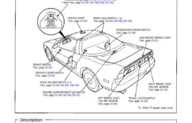
Component Location index
SRS components are located in this area. Review the SRS
component locations, precautions, and procedures in the
SRS section (24) before performing repairs or service.
SAFETY INDICATOR (In the gauge assembly)
Removal, page 23-129 (’93-’96) (’91-’92)
Troubleshooting, page 23-152 (’94-’96) (’91-’93)
Input Test, page 23-150 (’94-’96) (’93) (’91-’92)
CEILING LIGHT
Test, page 23-201
ROOF LOCK SWITCH ( * 1)
Test, page 23-154 (’94-’96) (’91-’93)
PASSENGER’S DOOR SWITCH
Test, page 23-204
HIGH MOUNT BRAKE LIGHT
Test, page 23-211
BRAKE SWITCH
Test, page 23-211
DRIVER’S DOOR SWITCH
Test, page 23-204
ROOF HOLDER SWITCH (* 1)
Test, page 23-155 (’94-’96) (’91-’93)
ENGINE COMPARTMENT LID SWITCH
Test, page 23-325 (’93-’96) (’91-’92)
LEFT BRAKE LIGHT
FAILURE SENSOR
Test, page 23-153
TRUNK LATCH SWITCH
Test, page 23-205
RIGHT BRAKE LIGHT
FAILURE SENSOR
Test, page 23-153
*1: NSX-T (open top) only
Description
Safety Indicator System:
LED’s are used to indicate when the trunk lid, engine compartment lid, a door, or the roof is not latched, or when a brake
light is faulty, or when the roof is not stored or improperly stored in its holder. The LED’s will go on and stay on for about
two seconds after the ignition switch has been turned ON, to show that the system circuit is functioning.
Brake Light Bulb Failure Indicator:
If all brake light bulbs are OK, the indicator light stays off because the ORN/WHT wire is grounded by the two brake light
failure sensors connected in series. With the brake lights off, the ground is provided through the diode, the failure sensor
relay coil, and bulb filaments. With the brake light on, all four relays (two in the left sensor, two in the right sensor), con-
nected in series, supply ground. If any of the four bulbs is not working, the chain is broken and the ORN/WHT wire is not
longer grounded. The indicator light comes on.