ABS Control Unit
Replacement
SRS components are located in this area. Review the SRS
component locations, precautions, and procedures in the
SRS section 24 before performing repairs or service.
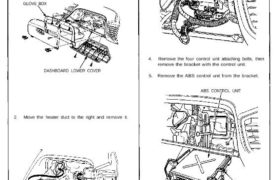
1. Remove the dashboard lower cover and glove box,
and disconnect the light connector.
GLOVE BOX
DASHBOARD LOWER COVER
2. Move the heater duct to the right and remove it.
HEATER DUCT
3. Disconnect the connectors from the ABS control unit
by removing the wire harness band.
ABS CONTROL UNIT
4. Remove the four control unit attaching bolts, then
remove the bracket with the control unit.
5. Remove the ABS control unit from the bracket.
ABS CONTROL UNIT
BRACKET
CONTROL UNIT
ATTACHING BOLTS
10 N-m (1.0 kg-m, 7 Ib-ft)
6. Installation is the reverse of removal procedure.
NOTE: After installation, start the engine and make
sure that the ABS indicator light goes off.
