Starting System
Starter Cut Relay Test
1. Remove the glove box (see section 20).
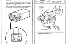
2. Disconnect the 4-P connector from the starter cut
relay.
(Wire colors of 4-P connector: BLK/GRN, BLK/
WHT, BLK/BLU and BLK/WHT)
3. Check continuity at the relay terminals.
• There should be continuity between the C and D
terminals.
• There should be continuity between the A and B
terminals when power and ground are connect-
ed to the C and D terminals.
• There should be no continuity between the A and
B terminals when power is disconnected.
Clutch Interlock Switch Test (M/T)
1. Remove the dashboard lower cover and knee bolster,
then disconnect the 2-P connector from the switch.
2. Check for continuity between the terminals accord-
ing to the table.
CLUTCH
INTERLOCK
SWITCH
CLUTCH PEDAL
3. If necessary, replace the switch or adjust the switch
position (see section 12).
