Lights-on Reminder Systen.
Chime Test
NOTE: Refer to page 23-158 (’93-’96) (’91-’92) for a dia-
gram of the lights-on reminder circuit, and page 23-166
for the input test of the circuit.
When the ignition key is turned off and removed with
the lights on, voltage is applied to the reminder circuit in
the integrated control unit. When you open the driver’s
door, the circuit senses ground through the closed door
switch. With voltage at the “A6” terminal, ground at the
“GRN/BLU2” terminal, and no voltage at the “A5” termi-
nal, the chime sounds to remind the driver to turn off
the lights.
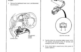
1. Remove the dashboard lower cover, and disconnect
the connectors.
DASHBOARD
LOWER
COVERCONNECTORS
CHIME
View from wire side
2. Test the chime by connecting battery power to the
“B” terminal, and ground to the “A” terminal, and
cycling the power on-off repeatedly.
3. If the chime fails to sound every time power is
cycled, replace it.
