Overhaul
1. Carefully clamp the gearbox in a vise with soft jaws.
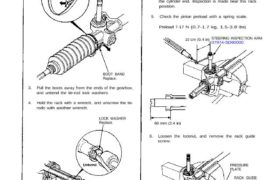
2. Remove the boot band.
BOOT BAND
Replace.
3. Pull the boots away from the ends of the gearbox,
and unbend the tie-rod lock washers.
4. Hold the rack with a wrench, and unscrew the tie-
rods with another wrench.
LOCK WASHER
Replace.
4. Before disassembly, install the special tool on the pin-
ion shaft and check the preload.
If the preload is out of the specification, adjust the
rack guide (page 17-27).
If the preload is still out of the specification, disas-
semble the gearbox and check each part.
NOTE: Slide the steering rack in the cylinder until
the end of the rack projects 60 mm (2.4 in) from
the cylinder end. Inspection is made near this rack
position.
5. Check the pinion preload with a spring scale.
Preload 7-17 N (0.7-1.7 kg, 1.5-3.8 Ibs)
10 cm (0.4 in) STEERING INSPECTION ARM
07974-SD90000
PRESSURE
PLATE
RACK GUIDE
SCREW
LOCKNUT
PRESSURE
SPRING
RACK GUIDE
60 mm (2.4 in)
6. Loosen the locknut, and remove the rack guide
screw.
7. Remove the set screw locknut.
CROW FOOT WRENCH,
SET SCREW
LOCKNUT
8. Remove the pinion set screw using the special tool.
Check the dust seal for damage and remove it if
it must be replaced. Refer to page 17-25 for in-
stallation.
PINION
SET SCREW
LOCKNUT WRENCH
07908-ME90000
9. Move the rack toward the gearbox side (i.e. in the
direction of the arrow) as far as it goes, then pull
the steering pinion out when the pinion gear clears
the cutout in the rack.
NOTE: The rack cannot be removed from the
cylinder side.
STEERING
PINION
GEARBOX
Arrow direction.
Check the pinion bearing movement while pull-
ing the bearing outer race as shown.
NOTE: This type of the bearing has play. The play
should not be excessive.
UPPER BALL
BEARING
OUTER RACE
(cont’d)
DUST SEAL
Manual Steering
Overhaul (Cont’d)
If the pinion bearing is noisy or has excessive
play, replace the bearing using the special tools
and a press.
NOTE: Hold the outer race with the tool securely.
Press
HUB DIS/ASSEMBLY BASE
07GAF-SD40700
BEARING
Press the steering pinion into the new pinion
bearing.
NOTE:
Install the pinion bearing with the wider side of
the inner race toward the gear.
Hold the inner race with the tool securely.
Press
Bearing mark
BEARING
HUB DIS/ASSEMBLY BASE
07GAF-SD40700
10. Remove the steering rack from the cylinder
housing.
NOTE: The steering rack cannot be removed from
the cylinder side.
STEERING RACK
CYLINDER
HOUSING
Check the lower bearing and replace it if it is
damaged.
Remove the lower bearing by lightly tapping
with a plastic hammer as shown. If the lower
bearing is hard to remove by tapping, heat the
gearbox by soaking it in 212°F (100°C) water.
CAUTION: To avoid burns, use heavy gloves when
handling the heated gearbox.
LOWER BEARING
Tap with a plastic hammer to
remove the bearing.
Press the new lower bearing into the gearbox
housing until it seats using a press and special
tool.
NOTE:
Install the lower bearing with the wider side of
the outer race toward the bottom of the
gearbox.
Hold the outer race with the tool securely.
Do not allow dust and other foreign materials to
enter the lower bearing.
Press
LOWER
BEARING
P/S ADJUSTMENT GUIDE
07973-6920001
11. Insert the steering rack into the cylinder housing,
being careful not to damage the steering rack
sliding surface.
STEERING RACK
CYLINDER
HOUSING
12. Install the steering pinion into the gearbox.
NOTE: Do not engage the steering pinion with the
steering rack this time.
STEERING PINION
GEARBOX
13. If the pinion dust seal was removed, drive in the
new dust seal until it bottoms on the step on the pi-
nion set screw.
14. Grease the sealing lip of the pinion dust seal.
PINION
SET SCREW PINION
DUST SEAL
Bottom here.Bottom here.
(cont’d)
Manual Steering
Overhaul (Cont’d)
1 5. Wrap the splined area of the steering pinion with
vinyl tape and grease the surface of the tape.
16. Slide the pinion set screw over the steering pinion,
being careful not to damage the sealing lip of the
dust seal, then remove the vinyl tape.
PINION
SET SCREWVINYL TAPE
17. Tighten the pinion set screw to a torque wrench
reading (indicated) of 9.4—10.4 N.m (94-104kg-
cm, 84—93 Ib-in).
NOTE: The above specification is the torque wrench
reading (indicated) when the set screw is tightened
using a torque wrench 25 cm (10 inches) long. If you
tighten the set screw using a torque wrench of the
different length, obtain the torque value using the
following formulas.
A/(A + B) = Y
Y x Actual torque = X
X = Torque wrench reading.
Indicated: 9.4—10.4 N.m
(94-104 kg-cm, 84-93 Ib-in)
Actual: 8.0-10 N.m (80-100 kg-cm, 82-87 Ib-in)
LOCKNUT WRENCH
07908-ME90000
18. Turn the pinion shaft right and left several times to
set it, then loosen the pinion set screw.
NOTE: Be sure that the pinion gear and rack gear
are not engaged.
PINION
SHAFT
PINION
SET SCREW
19. Install the special tool onto the pinion shaft. Attach
a spring scale to the tool and pull the scale. Adjust
the pinion set screw until the gauge reads 1.5—2.5
N (0.15-0.25 kg, 0.33-0.55 Ib).
STEERING INSPECTION ARM
07974-SD90000
PINION SHAFT
SPRING
SCALE
LOCKNUT WRENCH
07908-ME90000
20. Install the set screw locknut, then hold the pinion
set screw and tighten the set screw locknut.
SET SCREW
LOCKNUT
70-90 N.m
(7.0-9.0 kg-m, 50-65 Ib-ft)LOCKNUT WRENCH
07908-ME90000
CROW FOOT
21. Turn the pinion shaft slowly, then insert the rack
and engage the rack and pinion gears.
PINION SHAFT
22. The system is in neutral when the rack end projects
60 mm (2.4 in) from the cylinder end.
23. Install the rack guide, pressure plate, pressure
spring and rack guide screw.
60 mm (2.4 in)
PRESSURE
SPRING
PRESSURE
PLATE
RACK GUIDE
SCREW
LOCKNUT
24. Tighten, loosen and retighten the rack guide screw
two times to 5 N·m (0.5 kg-m, 3.6 Ib-ft), then back
it off 15°.
RACK GUIDE
(cont’d)
WRENCH.
Manual Steering
Overhaul (Cont’d)
25. Install the lock nut on the rack guide screw, and
en the locknut while holding the rack guide screw
with a wrench.
LOCKNUT
68 N·m (6.8 kg-m, 49 Ib-ft)
CROW FOOT
26. Screw each rack end into the rack while holding
the lock washer so its tabs are in the slots in the
rack end.
NOTE: Install the stopper washer with the cham-
fered side facing out.
Installation
direction.
LOCK WASHER
RACK END
STOPPER WASHER
27. Tighten the rack end securely, then bend the lock
washer back against the flat on the flange as shown.
NOTE: Coat the stopper
washer with grease suffi
ciently.
RACK END
55 N.m
(5.5 kg-m, 40 Ib-ft)
28. Install the boots on the rack end with the tube
clamps.
NOTE:
TUBE CLAMP
BOOT
STEERING GREASE
(Honda P/N 08733-B070E)
Coat the inside of the boot.
SILICONE GREASE
Coat the sliding
surface of the rack
end.
Coat the rack end and inside of the boot with the
grease.
Before installing the boot, be sure that the pres-
sure inside of the boot is the atmospheric
pressure.
Install the boot band with the rack in the straight
ahead condition (i.e. right and left tie-rods are
equal in length).
WRENCH,
29. Install the new boot bands on the boot and bend both
sets of locking tabs.
30. Lightly tap on the doubled portions to reduce their
height.
NOTE: After assembling, slide the rack right and left
to be certain that the boots are not deformed or
twisted.
31. If the tie-rod ends were removed, install the tie-
rods on the right and left rack ends and screw them
in until the threaded section is 11 mm (0.4 in) in
length.
BOOT BAND
11 mm (0.4 in)
TIE-ROD END
LOCKNUT
Hand tighten.
32. Install the gearbox on the front crossbeam (see
page 17-20).
33. Check the wheel alignment and adjust if necessary
(see section 18).