Shift Control Solenoid Valve A/B
Test
NOTE: Shift control solenoid valves A and B must be re-
moved/replaced as an assembly.
1. Disconnect the connector from the shift control sole-
noid valve A/B.
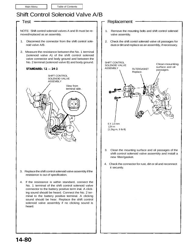
2. Measure the resistance between the No. 1 terminal
(solenoid valve A) of the shift control solenoid
valve connector and body ground and between the
No. 2 terminal (solenoid valve B) and body ground.
SHIFT CONTROL
SOLENOID VALVE
ASSEMBLY
View from
terminal side.
3. Replace the shift control solenoid valve assembly if the
resistance is out of specification.
4. If the resistance is within standard, connect the
No. 1 terminal of the shift control solenoid valve
connector to the battery positive term inal. A click-
ing sound should be heard. Connect the No. 2 ter-
minal to the battery positive terminal. A clicking
sound should be hear. Replace the shift control
solenoid valve assembly if no clicking sound is
heard.
3. Clean the mounting surface and oil passages of the
shift control solenoid valve assembly and install a
new filter/gasket.
4. Check the connector for rust, dirt or oil and reconnect
it securely.
6 X 1.0 mm
12N.m
(1.2kg-m, 9 Ib-ft)
FILTER/GASKET
Replace.
Clean mounting
surface and oil
passages.
SHIFT CONTROL
SOLENOID VALVE
ASSEMBLY
1. Remove the mounting bolts and shift control solenoid
valve assembly.
2. Check the shift contol solenoid valve oil passages for
dust or dirt and replace as an assembly, if necessary.
Replacement
Test
NOTE: Shift control solenoid valves A and B must be re-
moved/replaced as an assembly.
1. Disconnect the connector from the shift control sole-
noid valve A/B.
2. Measure the resistance between the No. 1 terminal
(solenoid valve A) of the shift control solenoid
valve connector and body ground and between the
No. 2 terminal (solenoid valve B) and body ground.
SHIFT CONTROL
SOLENOID VALVE
ASSEMBLY
View from
terminal side.
3. Replace the shift control solenoid valve assembly if the
resistance is out of specification.
4. If the resistance is within standard, connect the
No. 1 terminal of the shift control solenoid valve
connector to the battery positive term inal. A click-
ing sound should be heard. Connect the No. 2 ter-
minal to the battery positive terminal. A clicking
sound should be hear. Replace the shift control
solenoid valve assembly if no clicking sound is
heard.
3. Clean the mounting surface and oil passages of the
shift control solenoid valve assembly and install a
new filter/gasket.
4. Check the connector for rust, dirt or oil and reconnect
it securely.
6 X 1.0 mm
12N.m
(1.2kg-m, 9 Ib-ft)
FILTER/GASKET
Replace.
Clean mounting
surface and oil
passages.
SHIFT CONTROL
SOLENOID VALVE
ASSEMBLY
1. Remove the mounting bolts and shift control solenoid
valve assembly.
2. Check the shift contol solenoid valve oil passages for
dust or dirt and replace as an assembly, if necessary.
Replacement