Hydraulic Control
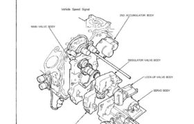
The valve bodies include the main valve body, regulator valve body, lock-up valve body, secondary valve body, servo
body, throttle valve body and 2nd accumulator body.
The oil pump is driven by splines on the left end of the torque converter which is attached to the engine. Oil flows through
the regulator valve to maintain specified pressure through the main valve body to the manual valve, and the servo body,
directing pressure to each of the clutches.
Vehicle Speed Signal
2ND ACCUMULATOR BODY
REGULATOR VALVE BODY
LOCK-UP VALVE BODY
SERVO BODY
THROTTLE VALVE BODYLINEAR SOLENOID
SECONDARY VALVE BODY
MAIN VALVE BODY
Throttle Valve Body
The throttle valve body is mounted on the servo valve body with the throttle valve built in.
LINEAR
SOLENOID
THROTTLE VALVE B
THROTTLE VALVE
BODY
Throttle Valve B, Linear Solenoid
Throttle valve B converts changes in the throttle opening to changes in transmission hydraulic pressure, to determine
transmission shift quality and lock-up operation. The throttle valve B also operates on accumulator back pressure to
make smooth changes from one gear to another.
The end of the valve contacts the linear solenoid which is controlled by the TCM.
The throttle pedal load has been reduced by eliminating the cable.
(cont’d)
LINEAR SOLENOID
Description
Hydraulic Control (cont’d)
Regulator Valve Body
The regulator valve body is mounted on the main valve body with the regulator valve, lock-up control valve and cooler
relief valve built in. The stator shaft arm contacts the end of the regulator valve.
The hydraulic pressure (line pressure) is controlled by the regulator valve.
COOLER RELIEF VALVE
REGULATOR VALVE
LOCK-UP CONTROL
VALVE
STATOR SHAFT ARM
REGULATOR VALVE
BODY
Regulator Valve
The regulator valve maintains a constant hydraulic pressure sent from the oil pump to the hydraulic control system, while
also furnishing oil to the lubricating system and torque converter.
Oil flows through B and B’. The oil which enters through B flows through the valve orifice to A pushing the regula* 01
valve to the right. According to the level of hydraulic pressure through B, the position of the valve changes, and the
amount of the oil through B’ from D also changes. This operation is continued, maintaining line pressure.
(ENGINE NOT RUNNING) (ENGINE RUNNING)
To TORQUE CONVERTER
Stator Reaction Hydraulic Pressure Control
Hydraulic pressure increase according to torque is performed by the regulator valve using stator torque reaction. The
stator shaft is splined in the stator and its arm end contacts the regulator spring cap. When the car is accelerating or
climbing (Torque Converter Range), stator torque reaction acts on the stator shaft and the stator arm pushes the regula-
tor spring cap in this direction in proportion to the reaction. The spring compresses and the valve moves to increase
the regulated control pressure or line pressure. Line pressure is maximum when the stator reaction is maximum.
To RELIEF VALVE
From OIL PUMP
STATOR SHAFT
(cont’d)
REGULATOR SPRING CAP
REGULATOR VALVE
Description
Hydraulic Control (cont’d)
Main Valve Body
The main valve body is located on the torque converter housing. The oil pump gear, torque converter check valve, manu-
al valve, 1 —2, 2—3, 3—4 shift valves, relief valve and one-way relief valve are all built into the main valve body.
The primary function of this valve body is switching on and off oil passages and controlling the hydraulic pressure going
to the hydraulic control system.
TORQUE COVERTER
CHECK VALVE
OIL PUMP DRIVEN GEAR
OIL PUMP DRIVE GEAR
MANUAL VALVE
DETENT SPRING
MAIN VALVE BODY
2-3 SHIFT VALVE
1-2 SHIFT VALVE
MANUAL VALVE
3-4 SHIFT
VALVE
ONE-WAY RELIEF
VALVE
RELIEF VALVE
Oil Pump
The external tooth gear type oil pump consists of a housing together with the main valve body, a pump drive gear, a
pump driven gear, and a pump shaft. The oil pump is installed on the torque converter housing. The pump’s driving force
is transmitted by the torque converter pump (directly connected to the engine) to the pump shaft. The gears are provided
in the housing. The intake and exhaust lines and the torque converter line are provided in the housing.
One way Relief Valve
The one-way relief valve is used at times of high speed or high temperature to send relief oil to the oil cooler so that
cooling of ATF will be effective.
(cont’d)
Description
Hydraulic Control (cont’d)
Secondary Valve Body
The secondary valve body is also mounted on the main valve body with the 3-2 kick-down valve, CPC valve, 2nd orifice
control valve, 3rd orifice control valve, modulator valve, 4th exhaust valve, 2nd exhaust valve, servo control valve and
4-3 kick-down valve built in.
Primarily, it regulates shift valve operation timing and clutch pressure for shock reduction during shifting.
MODULATOR VALVE
4TH EXHAUST VALVE
SERVO CONTROL VALVE
3-2 KICK-DOWN
VALVE
SECONDARY VALVE BODY
4-3 KICK-DOWN VALVE
2ND EXHAUST VALVE
CPC VALVE
2ND ORIFICE
CONTROL VALVE
3RD ORIFICE CONTROL
VALVE
Modulator Valve
The modulator valve maintains line pressure from the regulator that is supplied to shift control solenoid valves A/B and
lock-up control solenoid valves A/B, thus maintaining accurate shift and lock-up characteristics.
MODULATOR VALVE
2nd Orifice Control Valve
For smooth shifting between the 2nd and 3rd gear, the open pressure on the 2nd gear side is relieved through a fixed
orifice. The valve also moves to equalize pressure differences between the 2nd and 3rd gear.
2nd Exhaust Valve
The 2nd exhaust valve is installed to release 2nd clutch pressure quickly when shifting from the range at which hydraulic
pressure is applied to the 2nd clutch to the position.
2ND ORIFICE CONTROL VALVE
(cont’d)
2ND EXHAUST VALVE
Description
Hydraulic Control (cont’d)
Servo Body/2nd Accumulator Body
The servo body is mounted on the secondary valve body with the servo valve, 1st accumulator piston, 3rd accumulator
piston and 4th accumulator piston built in. The primary function of the servo body is forward and reverse switching and
control.
The 2nd accumulator body is mounted on the torque converter housing with the 1st-hold accumulator, 2nd accumulator
and limited slip differential relief valve built in.
1ST-HOLD ACCUMULATOR PISTON
2ND ACCUMULATOR PISTON
LIMITED SLIP DIFFERENTIAL
RELIEF VALVE
2ND ACCUMULATOR BODY
SERVO VALVE
1ST ACCUMULATOR PISTON
ATF STRAINER
Limited Slip Differential Relief Valve
When the resistance of oil flow inside the limited slip differential becomes large, the limited slip differential relief valve is
opened, and oil is sent to the ATF cooler and cooled.
4TH ACCUMULATOR
PISTON
3RD ACCUMULATOR
PISTON
SERVO BODY
Lock-up Valve Body
The lock-up valve body is mounted on the regulator valve body with the lock-up shift valve and lock-up timing B valve
built in.
The capacity of the lock-up clutch is controlled by the lock-up valve body.
LOCK-UP SHIFT VALVE
LOCK-UP VALVE
BODY
LOCK-UP TIMING B VALVE