Reassembly
1. Install the oil seal, shift arm, and shift lever in the
transmission housing.
8 x 1.0 mm SPECIAL BOLT
32 N.m (3.2 kg-m, 23 Ib-ft)
SPRING WASHER
SHIFT ARM
TRANSMISSION HOUSING
SHIFT LEVER
OIL SEAL
Replace.
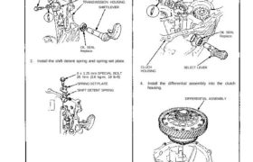
2. Install the shift detent spring and spring set plate.
8 x 1.25 mm SPECIAL BOLT
26 N.m (2.6 kg-m, 19 Ib-ft)
SPRING SET PLATE
SHIFT DETENT SPRING
3. Install the oil seal, select arm, and select lever in
the clutch housing.
8 x 1.0 mm SPECIAL BOLT
32 N·m (3.2 kg-m, 23 Ib-ft)
SPRING WASHER
SELECT ARM
OIL SEAL
Replace.
SELECT LEVERCLUCH
HOUSING
4. Install the differential assembly into the clutch
housing.
DIFFERENTIAL ASSEMBLY
CLUTCH HOUSING
(cont’d)
Transmission
Reassembly (cont’d)
5. Install the spring washer, then insert the mainshaft
and countershaft into the shift forks and install
them as an assembly.
NOTE: Tape the mainshaft spline before instal-
lation.
COUNTERSHAFT
ASSEMBLY
SPRING WASHER
6. Install the change holder assembly in the clutch
housing.
NOTE: Place the interlock finger in the groove of
the select arm.
SELECT
ARM
CHANGE HOLDER
ASSEMBLY
INTERLOCK FINGER
8. Shift the reverse synchro sleeve to the driven gear
side. Lift the mainshaft assembly and reverse idle
gear shaft assembly, then install the reverse shift
fork assembly.
REVERSE SHIFT FORK
ASSEMBLY
7. Lift the mainshaft assembly, then install the
reverse idle gear shaft assembly with the spring pin
matching the groove of the clutch housing.
REVERSE IDLE GEAR
SHAFT ASSEMBLY
SPRING PIN
GROOVE
MAINSHAFT
ASSEMBLY
6 x 1.0 mm SPECIAL BOLTS
15 N.m (1.5kg-m, 11 Ib-ft)
SHIFT FORK
ASSEMBLY
Tape the main-
shaft spline.
9. Install the reverse shift arm.
6 x 1.0 mm SPECIAL BOLTS
15 N.m (1.5kg-m. 11 Ib-ft)
REVERSE SHIFT ARM
10. Apply liquid gasket to the surface of the transmis-
sion housing mating with the clutch housing as
shown.
NOTE:
Use liquid gasket (P/N 08718-0001).
Remove the dirt oil from the sealing surface.
Seal the entire circumference of the bolt hole to
prevent oil leakage.
If 20 minutes have passed after applying liquid
gasket, reapply it and assemble the housings.
Refill the oil after 30 minutes after replacement.
Liquid gasket
SHIFT PIECE
SHIFT ARM
Neutral
position.
SHIFT LEVER
CLUTCH HOUSING
a. Place the shift lever as a shown.
DOWEL PINS
TRANSMISSION
HOUSING
3RD/4TH SHIFT FORK SHAFT COLLAR
11. Install the dowel pins on the clutch housing.
12. Place the transmission housing over the clutch
housing, being careful to line up the shafts.
NOTE: Make sure the 3rd/4th shift fork shaft col-
lar mates with the 3rd/4th shift fork shaft.
Groove
TRANSMISSION
HOUSING
(cont’d)
Transmission
Reassembly (cont’d)
b. Lower the transmission housing, then place the
shift arm in the groove of the shift piece by turn-
ing the shift lever.
TRANSMISSION HOUSING
SHIFT
ARM
SHIFT PIECE
SHIFT LEVER
c. Check the operation of the shift lever.
13. Lower the transmission housing with the snap ring
plier and set the snap ring in the groove of the
countershaft bearing.
SNAP RING
COUNTERSHAFT
BEARING
14. Check that the snap ring is securely seated in the
groove of the countershaft bearing.
Dimension A as installed: 1.60–8.15 mm
(0.063–0.321 in)
15. Tighten the transmission housing attaching bolts in
a criss-cross pattern in several steps shown below.
Torque: 45 N.m (4.5 kg-m, 33 Ib-ft)
16. Install the 36 mm sealing bolt.
NOTE: Apply liquid gasket (P/N 08718–0001) to
the flange.
17. Install the steel balls, springs, and sealing bolts.
NOTE: Apply liquid gasket (P/N 08718–0001) to
the threads, but don’t plug the hole with liquid
gasket.
14 x 1.0 mm SEALING BOLT
33 N.m (3.3 kg-m. 24 Ib-ft)
STEEL BALL
(3/8 in)
SPRING (L. 25 mm)
36 mm SEALING BOLT
35 N.m (3.5 kg-m, 25 Ib-ft)
SPRING
(L. 25.1 mm)
SPRING
(L. 30 mm)
16 x 1.0 mm
SEALING
BOLTS
42 N.m
(4.2 kg-m,
30 Ib-ft)
STEEL BALLS
(5/16 in)
SPRING
(L. 30 mm)
18. Install the back-up light switch and neutral position
switch.
NOTE: Apply liquid gasket (P/N 08718–0001) to
the threads.
19. Install the vehicle speed sensor (VSS).
6 x 1.0 mm
12 N.m (1.2 kg-m, 9 Ib-ft)
VSS
(O-RING Replace.)
8 x 1.25 mm
24 N.m (2.4 kg-m, 17 Ib-ft)
NEUTRAL POSITION
SWITCH
25 N.m (2.5 kg-m,
18 Ib-ft)
BACK-UP LIGHT SWITCH
25 N.m (2.5 kg-m,18 Ib-ft)
8×1.25 mm
24 N.m (2.4 kg-m, 17 Ib-ft)
8 x 1.25 mm
26 N.m (2.6 kg-m,
19 Ib-ft)