Function and Operation
Steering Sensor
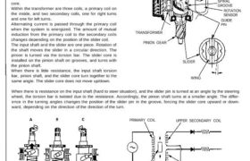
The steering sensor consists of a torque sensor, an
interface, and the rotation sensor.
Torque Sensor
The torque sensor converts steering torque input and its
direction to voltage signals, in conjunction with the
interface.
A torsional force caused by steering operation is con-
verted to an axial movement of a slider core. A variable
differential transformer is installed around the slider
core.
Within the transformer are three coils, a primary coil on
the inside, and two secondary coils, one for right turns
and one for left turns.
Alternating current is passed through the primary coil
when the system is energized. The amount of mutual
induction from the primary coil to the secondary coils
changes depending on the position of the slider coil.
The input shaft and the slider are one piece. Rotation of
the shaft moves the slider in a circular direction. The
pinion is turned via the torsion bar. The slider core is
installed on the pinion shaft on grooves, and turns with
the pinion shaft.
When there is little resistance, the input shaft torsion
bar, pinion shaft, and the slider core turn together to the
same angle. The slider core does not move up/down.
TORSION BAR
INPUT
SHAFT
INTERFACE
CIRCUIT
SPIRAL
GROOVE
ROTATION
SENSOR
GUIDE
PIN
TRANSFORMER
PINION GEAR
WING
When there is resistance on the input shaft (hard to steer situation), and the slider pin is turned at an angle by the steering
wheel, the torsion bar is twisted due to the resistance. Accordingly, the pinion shaft turns at a smaller angle. The differ-
ence in the turning angles changes the position of the slider pin in the groove, forcing the slider core upward or down-
ward, depending on the direction of the direction of the turn.
PRIMARY COIL UPPER SECONDARY COIL
LOWER SECONDARY COIL
SLIDER
SLIDER
Rotation Sensor
The rotation sensor is housed inside the steering gearbox near the pinion. It converts the rotation speed and direction of
steering into voltage signals. The rotation of the steering wheel is transmitted to the pinion, which drives the sensor by
accelerating its speed through the three pieces of transmission the gears. Acting as a kind of direct current generator, the
sensor generates direct current voltage proportionately with the rotational speed of the pinion. When the steering direc-
tion is reversed, the voltage is generated in the opposite direction. No power is generated when driving straight ahead
without turning the steering wheel.
Interface Circuit
The interface circuit is housed inside the steering gearbox near the pinion. It rectifies and amplifies the signals from the
torque sensor and the rotation sensor, and transmits the steering signals to the EPS control unit. A phase compensating
circuit is also built in, which changes the output signals in accordance with the drive signals input from the EPS control
unit.
TRANSMISSION GEARS
INTERFACE CIRCUIT
ROTATION SENSOR
System Description
Function and Operation
EPS Control Unit
The control unit receives input signals from the car’s speed sensors, torque sensor and rotation sensor. It performs a mul-
titude of control functions, including a circuit which can detect troubles in each functional part of the system and the con-
trol unit itself. The control unit operates the system while the engine is in the process of starting, on receipt of voltage
generated by the alternator. The system remains operational if the engine stalls with the ignition switch in ON (II) position.
Basic Control
(1) Travelling speeds are compiled into data, receiving input signals from the car’s speed sensors.
(2) The magnitude and direction of torque are compiled into data, receiving input signals from the torque sensor.
(3) The rotational speed and direction of steering are compiled into data, receiving input signals from the rotation sensor.
(4) Determination of motor torque data from the prescribed assisting force map, based on the car speed data, steering
rotational speed data and the steering torque data.
(5) Changeover of control modes based on data on car speed, direction of torque and rotational direction of steering.
Normal Control Mode:
The rotational direction of motor is determined after changing over to the left/right steering mode in accordance with
torque direction data. The mode is switched to the straight ahead mode when the output data is zero.
Return Control Mode:
According to torque direction data and steering rotational direction data, the mode is changed over to the return control
mode to improve the steering return characteristic.
Damper Control Mode:
According to car speed data, torque value data and steering rotational speed data, the mode is changed over to the
damper control mode to improve the convergence property of the steering.
Rotation sensor Torque sensor
Steering rotation duty Unloader duty
(Reduces over-current flow
at full-lock position)
Output duty Torque duty
Mode changeover
• Normal mode
• Return mode
• Damper mode
Motor control
signal output
Base duty
Car speed sensors
Self-Diagnosis Function
The EPS control unit monitors the system inputs and outputs, and the driving current of the motor. If there is a problem in
the system, the control unit turns the system off by actuating the relay. Power assist stops and normal manual steering
operation resumes. The control unit also turns the EPS indicator light on to alert the driver, and memorizes the problem in
the form of a code. Connecting the terminals of the service check connector with the SCS service connector (special tool)
enables the EPS indicator light to blink the problem code when the ignition switch is turned on (II).
Unloader Control
If the steering wheel is turned fully and held in the full-lock position, the steering torque reaches the maximum point, and
an over-current flows to the motor. The control unit detects this and reduces the current flow to the motor.
Average Moving Current Control
The electric current flow to the motor is estimated from the current values detected by the current sensor, and the average
current is obtained at two second intervals. The motor driving current is suppressed when the average current value
exceeds a predetermined marginal value. The control unit regulates the motor current during continuous loading to sup-
press any excessive temperature rise in the motor.
Over-Voltage Control
If there is an excessive increase in power source voltage due to a poor battery condition, an alternator voltage regulator
problem, etc., the motor assisting force increases, resulting in excessive control. To prevent this, the control signals are
corrected to ensure that adequate assisting force is generated.
System Description
Function and Operation
The control unit consists of a driving circuit, current sensor, field effect transistor (FET) bridge circuit, and two relays. It
receives control signals from the central processing unit (CPU) and controls the driving current of the motor. The driving
circuit controls the rotational direction and speed of the motor by driving the FET bridge circuit with a pulse width modu-
lation (PWM) method on receipt of an input of driving signals from the EPS control unit.
Rotational Speed Control
The PWM driving signal is a digital signal repeating the process of voltage ON/OFF at a constant frequency, which
changes the ratio of ON time per one cycle of this signal. The ratio is called the duty ratio. When there is a change in duty
ratio, the average voltage changes as smoothly as an analog type. The ratio of digital signal voltage (E) and the average
voltage (V) is called the duty ratio (8). Its relationship is expressed by V = E x 8. When the duty ratio is low, the rotational
speed of motor is slow. As the duty ratio increases, the rotational speed increases to increase the torque.
(Motor rotational speed slow)
ONE CYCLE
(Motor rotational speed fast)
ONE CYCLE
AVERAGE /
VOLTAGE (40%)
VOLTAGE APPLIED RATIO
IN ONE CYCLE: 40%
RELAY
CONTROL
SIGNALS
VOLTAGE APPLIED RATIO
IN ONE CYCLE: 60%
AVERAGE
VOLTAGE (60%)
FROM
BATTERY
POWER
RELAY
CURRENT
SENSOR
Rotational Direction Control
Normal Mode Control:
The table below shows the normal control mode to con-
trol the flow of current from the battery:
CURRENT
FEED BACK
DRIVE
SIGNAL
FET DRIVE
CIRCUIT
GROUND FAIL SAFE
RELAY
(“PWM” in the table indicates PWM control based on
torque sensor data).
Return Control Mode:
Return control mode improves the steering return char-
acteristics. (“PWM” in the table denotes PWM control
based on torque sensor data while “PWM-r” PWM con-
trol based on rotation sensor).
Damper Control Mode:
The damper mode control, which improves the convergence of steering, is performed with damper mode signals from the
control unit. In this mode, a short current circuit is formed on the motor side by turning off FET (1) and (2), and turning on
FET (3) and (4), which suppresses the returning speed of the steering.
Motor Driving Current Control
A current sensor, power relay and fail-safe relay are built into the control unit. The current sensor detects motor driving
current. If there is a problem in the system, a cut-off signal is sent from the CPU to relay, then the relay cuts off motor cur-
rent to switch to manual steering operation.
CONTROL UNIT
Steering Gearbox
Motor and Power Assist Mechanism
A motor is housed inside the gearbox housing. It consists of a yoke with a permanent magnet fixed in it, a rotor with a
field coil, and brushes which pass electricity to rotor commutators. The motor is on the rack shaft of the steering gearbox.
The drive current from the control unit flows through the power relay and fail-safe relay to the brushes of the motor.
The drive current flows to rotor commutators through brushes, exciting the field coil of the rotor and rotates the rotor with
the magnetic action of the permanent magnet inside the yoke. The rotor rotates in the opposite direction when the direc-
tion of drive current is reversed.
The rotation torque of the motor is transmitted to the ball screw through the helical gear. The rotation torque on the ball
screw is converted into assist thrust in the direction of steering rack by the recirculating ball screw. The mechanical advan-
tage of the recirculating ball screw, compaired to a conventional rack and pinion, acts to reduce the steering force to the
steering rack through the joint, to lessen the steering effort required at the steering wheel.
ROTOR RACK
RECIRCULATING
BALL SCREW
BALL SCREW
HELICAL GEAR
Recirculating Ball Screw
The recirculating ball screw is constructed so that steel balls roll between the screw shaft and the nut, and those coming
out of the screw face enter the screw groove again through a tube for recirculation. The rotation torque on the shaft is
converted into thrust in an axial direction as the slope of the screw shaft presses against the nut through the steel balls.
Since the torque conversion is made in this method through the screw shaft and the steel balls, the friction is small, high
transmission efficiency is obtained for both the forward and backward directions, and the steering feels identical to the
ordinary manual steering.
Furthermore, since the force from the backward direction (force pressing the steering rack) is converted into the rotation
torque of the screw shaft, instantaneous kick-back from the road surface will rapidly rotate the motor. In such a rapid rota-
tion, the inertia of the motor increases, which acts to reduce the kick-back. Any great kick-back will be transmitted from the
steering rack to the torque sensor on the pinion, which acts to twist the pinion shaft in the same direction as the input
direction of kick-back. As a result, the motor operates the kick-back to reduce assist force.
BALL SCREW
TUBE STEEL BALL
NUT