Category: Electrical
Categories
nsxb23272a.pdf
Power Windows Control Unit Input Test NOTE: The control unit only controls the driver’s door window. Remove the driver’s door panel and disconnect the 4-P and 6-P connectors from the control unit. Inspect the connector and socket terminals to be sure they are all making good contact. • If the terminals are bent, loose, or […]
Categories
nsxb23075a.pdf
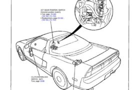
Starting System Component Location index A/T GEAR POSITION SWITCH (Neutral position switch) Test page 23-160 (’93-’96) (’91-’92) Replacement, page 23-161 . (’93-’96) (’91-’92) CLUTCH INTERLOCK SWITCH (M/T) Test, page 23-80 STARTER Test page 23-78 Solenoid Test, page 23-81 Replacement, page 23-81 Overhaul, page 23-82 Reassembly. page 23-87 STARTER CUT RELAY Wire colors: BLK/WHT, BLK/BLU. BLK/WHT […]
Categories
nsxe23273a.pdf
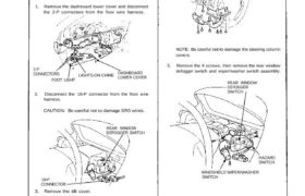
Switch Removal CAUTION: All SRS electrical wiring harnesses are covered with yellow outer insulation. Before disconnecting the SRS wire harness, install the short connector on the airbag (see page 23-323). Replace the entire affected SRS harness assembly if it has an open circuit or damaged wiring. 1. Remove the dashboard lower cover and disconnect the […]
Categories
nsxb23137a.pdf
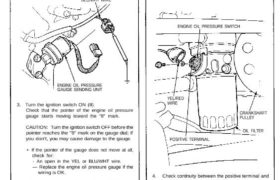
Engine Oil Pressure Gauge Gauge Test 1. Before testing, check the No. 5 (1 5 A) fuse in the under-dash fuse box. 2. Make sure the ignition switch is OFF, then discon- nect the 2-P connector from the engine oil pressure sending unit, and ground it with a jumper wire. BLU/WHT WIRE ENGINE OIL PRESSURE […]
Categories
nsxb23134a.pdf
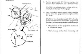
Fuel Gauge Gauge Test 1. Before testing, check the No. 5 (15 A) fuse in the under-dash fuse box. 2. Remove the rear bulkhead panel behind the driver’s seat, then remove the access panel. 3. Disconnect the 3-P connector from the fuel gauge sending unit. ACCESS PANEL 4. Connect the voltmeter positive probe to the […]
Categories
nsxb23096a.pdf
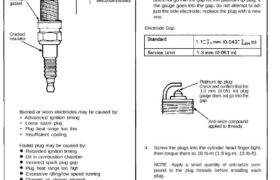
Ignition System Spark Plug Inspection 1. Inspect the electrodes and ceramic insulator for: Worn or deformed electrodes Damaged gasket • Improper gap • Oil-fouling • Carbon deposits • Cracked center electrode insulator Cracked insulator Burned or worn electrodes may be caused by: • Advanced ignition timing • Loose spark plug • Plug heat range too […]
Categories
nsxb23246a.pdf
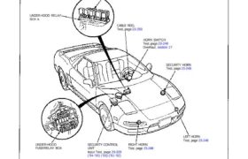
Horns Component Location Index SRS components are located in this area. Review the SRS component locations, precautions, and procedures in the SRS section (24) before performing repairs or ser- vice. HORN RELAY Test, page 23-249 UNDER-HOOD RELAY BOX A CABLE REEL Test, page 23-250 HORN SWITCH Test, page 23-249 Overhaul, section 17 SECURITY HORN Test, […]
Categories
nsxd23010a.pdf
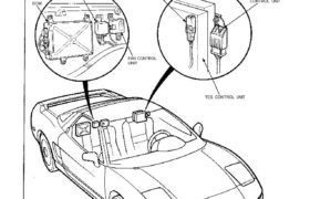
Relay and Control Unit Locations Rear Bulkhead FAN CONTROL UNIT ECM TCS FAIL-SAFE RELAY Wire colors: YEL, and LT GRN/BLK TRANSMISSION CONTROL MODULE (TCM) DASH LIGHTS BRIGHTNESS CONTROL UNIT TCS CONTROL UNIT GRN/RED, RED/BLK, RETRACTABLE HEADLIGHT CONTROL UNIT INTERLOCK CONTROL UNIT (A/T) FUEL PUMP RELAY Wire colors: YEL, RED, BLK/YEL, and BLK/RED 23-11 Attachments nsxd23010a […]
Categories
nsxb23070a.pdf
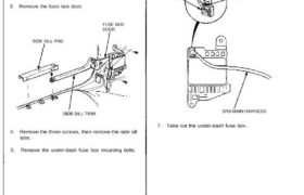
Under-dash Fuse Box Removal/Installation SRS components are located in this area. Review the SRS component locations, precautions, and procedures in the SRS section 24 before performing repairs or service. Removal: 1. Disconnect both the negative cable and positive cable from the battery. 2. Carefully remove the side sill pad (pull it up, rear end first). […]
Categories
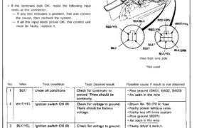
nsxb23211a.pdf
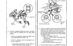
(G551) ’95-’96 Models. (G401,G402,G551) ’93-94 Models or Brake Switch Test 1. If one of the brake lights does not go on, check that brake light bulb in the taillight or the high mount light 2. If none of the brake lights 90 on, check the No. 45 (20 A) fuse in the under-hood fuse/relay box. […]