Category: Electrical
nsxb23241a.pdf
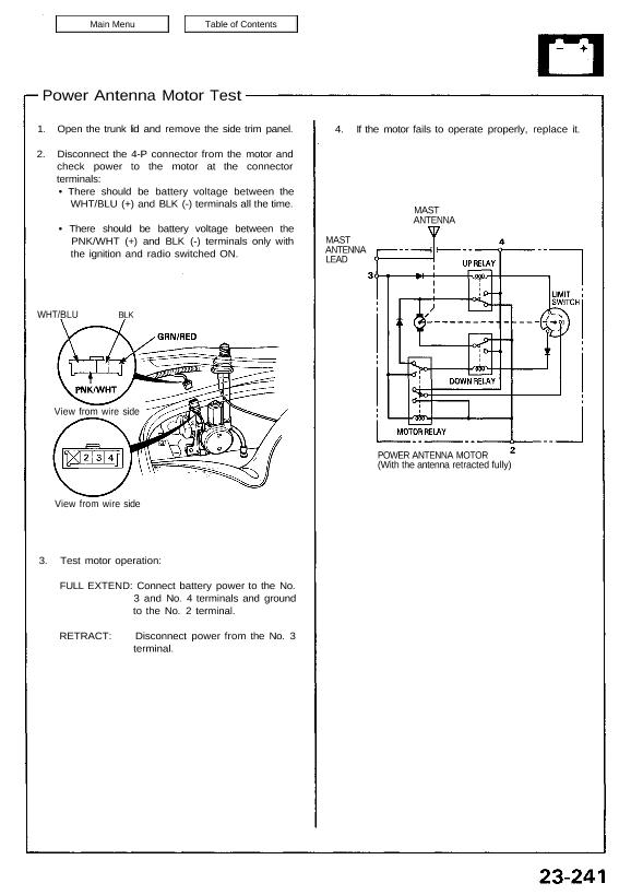
Power Antenna Motor Test 1. Open the trunk lid and remove the side trim panel. 2. Disconnect the 4-P connector from the motor and check power to the motor at the connector terminals: • There should be battery voltage between the WHT/BLU (+) and BLK (-) terminals all the time. • There should be battery […]
nsxb23293a.pdf
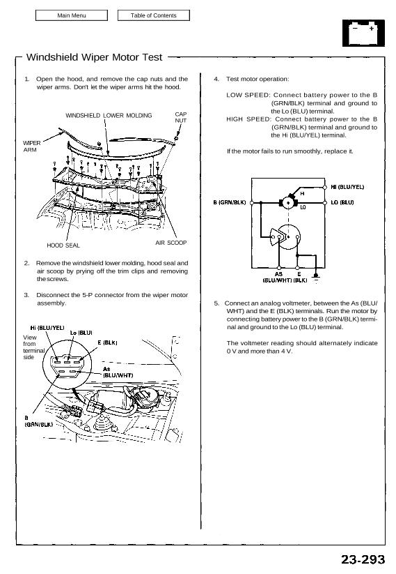
Windshield Wiper Motor Test 1. Open the hood, and remove the cap nuts and the wiper arms. Don’t let the wiper arms hit the hood. WIPER ARM WINDSHIELD LOWER MOLDING HOOD SEAL AIR SCOOP 2. Remove the windshield lower molding, hood seal and air scoop by prying off the trim clips and removing the screws. […]
nsxb23005a.pdf
Five-step Troubleshooting 1. Verify The Complaint Turn on all the components in the problem circuit to verify the customer complaint. Note the symp- toms. Do not begin disassembly or testing until you have narrowed down the problem area. 2. Analyze The Schematic Look up the schematic for the problem circuit. Determine how the circuit is […]
nsxb23201a.pdf
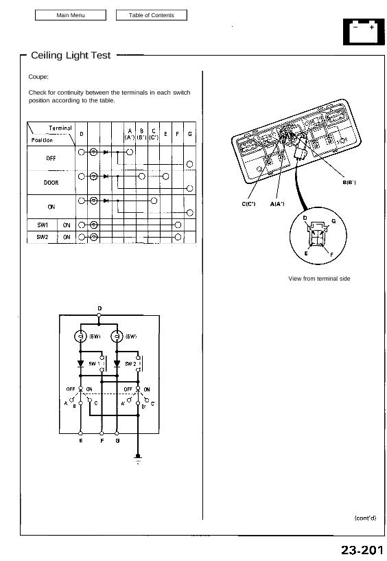
Ceiling Light Test Coupe: Check for continuity between the terminals in each switch position according to the table. View from terminal side Ceiling/Courtesy/Trunk Lights Ceiling Light Test NSX-T (open top): Check for continuity between the terminals in each switch position according to the table. Attachments nsxb23201a (60 kB)
nsxe23173a.pdf
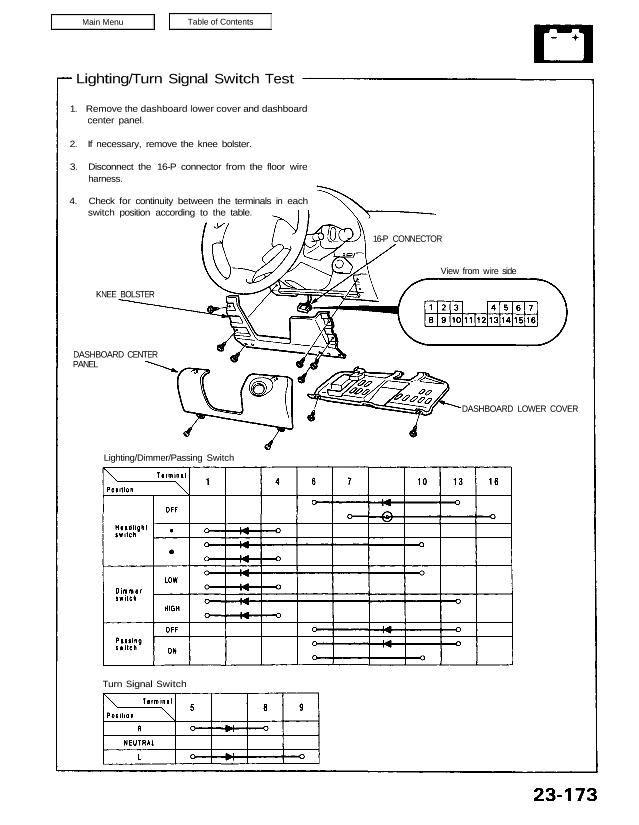
Lighting/Turn Signal Switch Test 1. Remove the dashboard lower cover and dashboard center panel. 2. If necessary, remove the knee bolster. 3. Disconnect the 16-P connector from the floor wire harness. 4. Check for continuity between the terminals in each switch position according to the table. KNEE BOLSTER DASHBOARD CENTER PANEL Lighting/Dimmer/Passing Switch Turn Signal […]
nsxd23095a.pdf
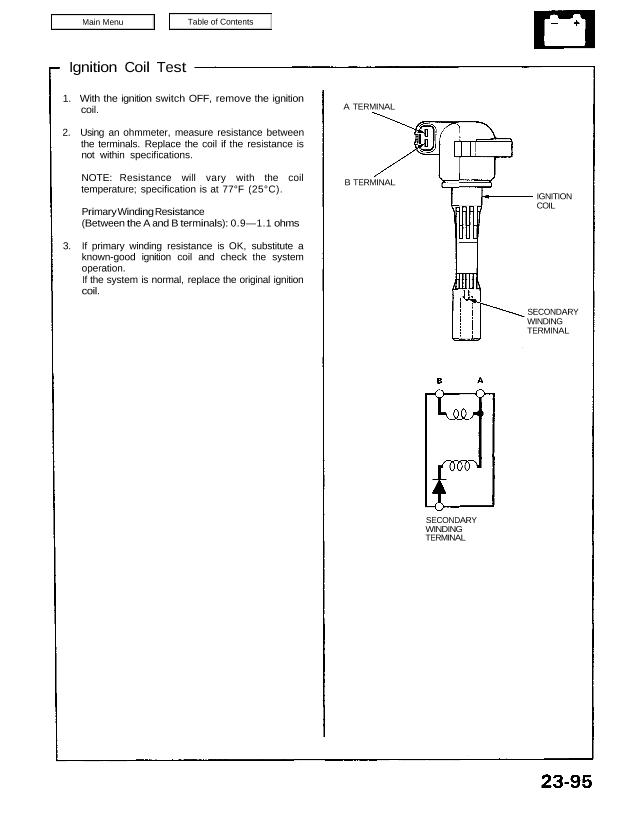
Ignition Coil Test 1. With the ignition switch OFF, remove the ignition coil. 2. Using an ohmmeter, measure resistance between the terminals. Replace the coil if the resistance is not within specifications. NOTE: Resistance will vary with the coil temperature; specification is at 77°F (25°C). Primary Winding Resistance (Between the A and B terminals): 0.9—1.1 […]
nsxb23116a.pdf
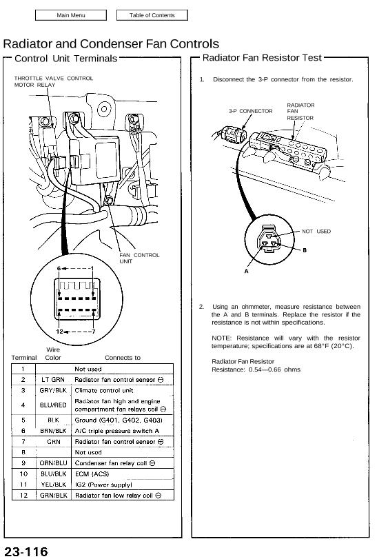
Radiator and Condenser Fan Controls Control Unit Terminals THROTTLE VALVE CONTROL MOTOR RELAY Wire Terminal Color Connects to 1. Disconnect the 3-P connector from the resistor. RADIATOR 3-P CONNECTOR FAN RESISTOR NOT USED 2. Using an ohmmeter, measure resistance between the A and B terminals. Replace the resistor if the resistance is not within specifications. […]
nsxb23195a.pdf
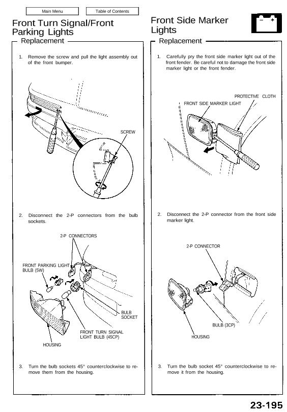
Front Turn Signal/Front Parking Lights Replacement 1. Remove the screw and pull the light assembly out of the front bumper. SCREW 2. Disconnect the 2-P connectors from the bulb sockets. 2-P CONNECTORS FRONT PARKING LIGHT BULB (5W) BULB SOCKET FRONT TURN SIGNAL LIGHT BULB (45CP) HOUSING 3. Turn the bulb sockets 45° counterclockwise to re- […]
nsxe23127a.pdf
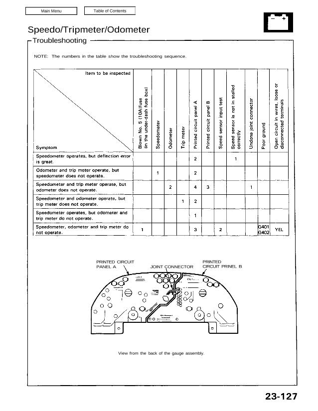
Speedo/Tripmeter/Odometer Troubleshooting NOTE: The numbers in the table show the troubleshooting sequence. PRINTED CIRCUIT PANEL A JOINT CONNECTOR PRINTED CIRCUIT PRINEL B View from the back of the gauge assembly. Attachments nsxe23127a (157 kB)
nsxb23274a.pdf
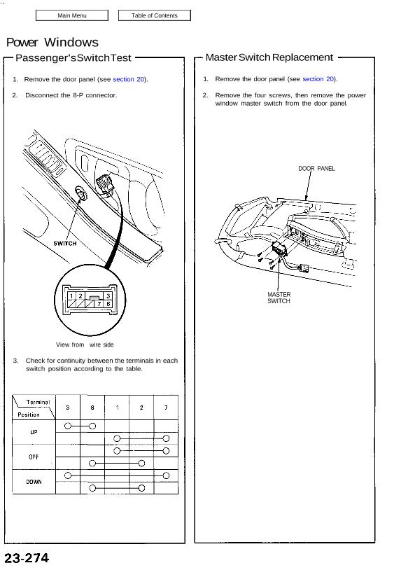
Power Windows Passenger’s Switch Test 1. Remove the door panel (see section 20). 2. Disconnect the 8-P connector. View from wire side 3. Check for continuity between the terminals in each switch position according to the table. Master Switch Replacement 1. Remove the door panel (see section 20). 2. Remove the four screws, then remove […]