Category: Electrical
nsxd23008a.pdf
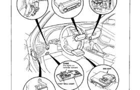
Relay and Control Unit Locations Dashboard CLIMATE CONTROL UNITTURN SIGNAL/HAZARD RELAY UNDER-DASH FUSE BOX INTEGRATED CONTROL UNIT DASHBOARD LOWER COVER STARTER CUT RELAY Wire colors: BLK/WHT BLK/WHT, BLU/GRN, and BLK/BLU Attachments nsxd23008a (178 kB)
nsxb23222a.pdf
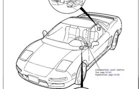
Dash Lights Brightness Control Component Location Index TRANSMISSION CONTROL MODULE (TCM) DASH LIGHTS BRIGHTNESS CONTROL UNIT Input Test, page 23-224 COMBINATION LIGHT SWITCH Test, page 23-181 Replacement, page 23-182 DASH LIGHTS BRIGHTNESS CONTROLLER Test, page 23-226 HEADLIGHT RETRACTOR SWITCH Attachments nsxb23222a (52 kB)
nsxb23067a.pdf
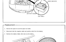
Battery Component Location Index BATTERY Type: 80D26L (A/T) 70D23L (M/T) CHECK INDICATOR HEAT SHIELD Replacement 1. Remove the spare tire and the spare tire holder. 2. Disconnect both the negative cable and positive cable from the battery. 3. Remove the battery holder, then take out the battery. SPARE TIRE SPARE TIRE HOLDER BATTERY HOLDER Attachments […]
nsxb23296a.pdf
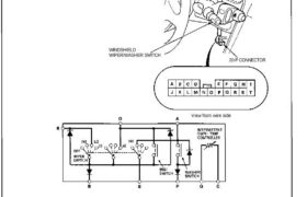
Wipers/Washers Windshield Wiper/Washer Switch Test 1. Remove the dashboard lower cover (see page 23-294). 2. Disconnect the 20-P connector from the floor wire harness. 3. Check for continuity between the terminals in each switch position according to the table. WINDSHIELD WIPER/WASHER SWITCH 20-P CONNECTOR View from wire side Attachments nsxb23296a (45 kB)
nsxb23252a.pdf
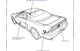
Trunk Opener Component Location Index TRUNK OPENER MAIN SWITCH Test, page 23-253 (’94-’96) (’93) (’91-’92) TRUNK OPENER SWITCH Test, page 23-254 TRUNK LATCH TRUNK OPENER SOLENOID Test/Replacement, page 23-254 Attachments nsxb23252a (41 kB)
nsxb23253a.pdf
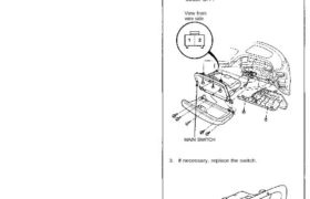
Main Switch Test 1. Remove the glove box, and disconnect the 2-P con- nector from the switch. 2. Check for continuity between the terminals. • There should be continuity between the No. 1 terminal and No. 2 terminal with the main switch ON. • There should be no continuity with the main switch OFF. View […]
nsxe23209a.pdf
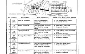
Cancel Unit Input Test Remove the steering column covers. Disconnect the 10-P connector from the cancel unit. Make the following input tests at the 10-P connector ter- minals. If all tests prove OK, but the turn signal lights fails to work, replace the cancel unit. CANCEL UNIT 10-P CONNECTOR TURN SIGNAL SWITCH C10(BLK) C8(BLU/GRN) C6(GRY) […]
nsxe23286a.pdf
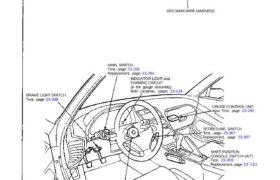
Cruise Control CAUTION: All SRS electrical wiring harnesses are covered with yellow outer insulation. Before disconnecting the SRS wire harness, install the short connector on the airbag (see page 23-323). Replace the entire affected SRS harness assembly if it has an open circuit or damaged wiring. SRS MAIN WIRE MARNESS MAIN SWITCH Test, page 23-295 […]
nsxb23206a.pdf
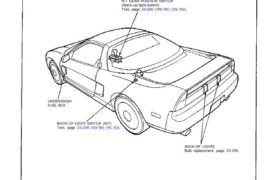
Back-up Lights Component Location Index A/T GEAR POSITION SWITCH (Back-up light switch) Test, page 23-160 (’93-’96) (’91-’92). UNDER-DASH FUSE BOX BACK-UP LIGHT SWITCH (M/T) Test, page 23-208 (’93-’96) (’91-’92). BACK-UP LIGHTS Bulb replacement, page 23-206 Attachments nsxb23206a (40 kB)
nsxb23231a.pdf
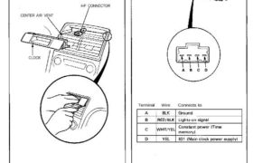
Removal CAUTION: Be careful not to damage the center air vent or clock. 1. Pull the clock out with your fingers (if necessary, use a screwdriver). 2. Disconnect the 4-P connector from the clock. 4-P CONNECTOR CENTER AIR VENT Terminals Terminal Wire Connects to CLOCK Attachments nsxb23231a (44 kB)