Snap-on CF711
Valves, Valve Springs and Valve Seals
Replacement
NOTE: Identify valves and valve springs as they are re-
moved so that each item can be reinstalled in its original
position.
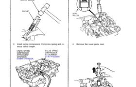
1. Using an appropriate-sized socket and plastic mallet,
lightly tap the valve retainer to loosen the valve keep-
ers before installing the valve spring compressor.
PLASTIC MALLET
SOCKET
2. Install spring compressor. Compress spring and re-
move valve keeper.
VALVE SPRING
COMPRESSOR
ATTACHMENT
EXTENSION
07MAF–PR9010A
VALVE SPRING
COMPRESSOR
ATTACHMENT
07757–PJ1010A
3. Install the special tool as shown.
VALVE SEAL COMMERCIALLY AVAILABLE
VALVE GUIDE SEAL REMOVER
LISLE P/N 57900 OR KD 3350
SEAL
PULLER
4. Remove the valve guide seal.
Intake Valve Dimensions
A Standard (New): 34.9 — 35.1 mm
(1.374-1.382 in)
B Standard (New): 111.05-111.40 mm
(4.372-4.386 in)
C Standard (New): 5.475—5.485 mm
(0.2156-0.2159 in)
C Service Limit: 5.445 mm (0.2144 in)
D Standard (New): 1.05—1.35 mm
(0.041-0.053 in)
D Service Limit: 0.85 mm (0.033 in)
Exhaust Valve Dimensions
A Standard (New): 29.9—30.1 mm
(1.177-1.185 in)
B Standard (New): 109.60-109.90 mm
(4.315-4.327 in)
C Standard (New): 5.45-5.46 mm
(0.2146-0.2150 in)
C Service Limit: 5.42 mm (0.2134 in)
D Standard (New): 1.65—1.95 mm
(0.065-0.077 in)
D Service Limit: 1.45 mm (0.057 in)
Cylinder Head Height;
Standard (New): 150.95-151.05
(5.943-5.947 in)
Service Limit: 150.8 mm (5.937 in)
Measure along edges, and 3 ways across center.
NOTE: If camshaft-to-holder oil clearances (page 6-38)
are not within specification, the head cannot be
resurfaced.
If camshaft-to-holder oil clearances are within
specifications, check the head for warpage.
Cylinder Heads
Warpage
If warpage is less than 0.05 mm (0.002 in) cylinder
head resurfacing is not required.
If warpage is between 0.05 mm (0.002 in) and 0.2
mm (0.008 in), resurface cylinder head.
Maximum resurface limit is 0.2 mm (0.008 in) based
on a height of 151 mm (5.945 in).
PRECISION STRAIGHT EDGE
