Control Unit Input Test
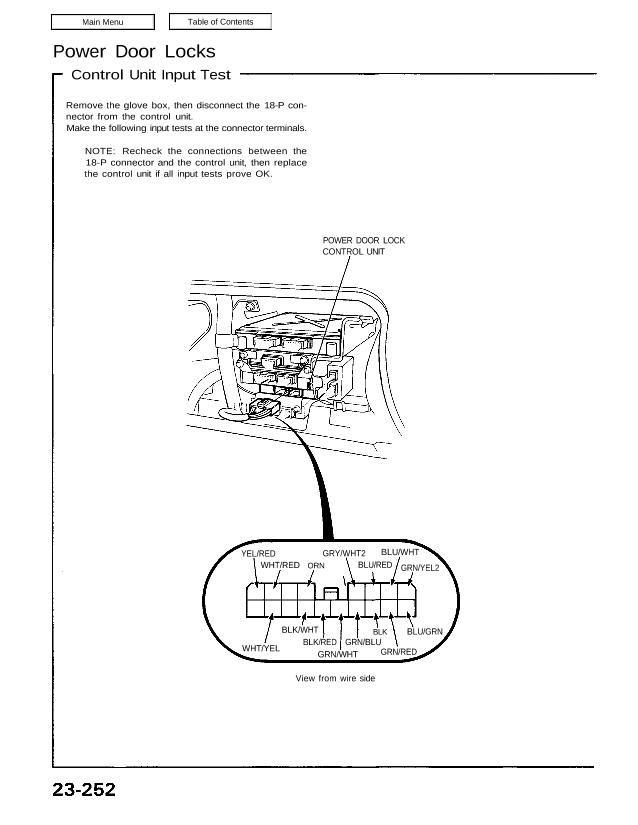
Remove the glove box, then disconnect the 18-P con-
nector from the control unit.
Make the following input tests at the connector terminals.
NOTE: Recheck the connections between the
18-P connector and the control unit, then replace
the control unit if all input tests prove OK.
POWER DOOR LOCK
CONTROL UNIT
YEL/RED
WHT/RED ORN
GRY/WHT2
BLU/RED
BLU/WHT
GRN/YEL2
WHT/YEL
BLK/WHT
BLK/RED
GRN/WHT
GRN/BLU
BLK
GRN/RED
BLU/GRN
View from wire side
CAUTION: To prevent damage to the motor, apply battery voltage only momentarily.
Main Menu Table of Contents
No. Wire Test condition Test: desired result Possible cause (if result is not obtained)
Under all conditions. Check for continuity to I Poor ground (G401, 402)
1 BLK ground: There should be I An open in the wire.
continuity.
Under all conditions. Check for voltage to ground: I Blown No. 35 (20A) fuse.
2 ORN There should be battery I An open in the wire.
voltage.
GRN/WHTZ Driver’s door lock Check for voltage to ground: I Faulty driver’s door lock switch.
3 switch in LOCK. There should be 1 V or less. I Poor ground (G401, 402).
WHT/YEL ∣⊃↾⋮∀⋮∣∙⋅≊ door lock I An open In the Wire.
switch in UNLOCK.
BLK/WHT Passenger’s door lock Check for voltage to ground: I Faulty passenger’s door lock
4 switch in LOCK. There should be 1 V or less. switch.
. I Poor ground (G401, 402).
ELK/RED Passenger 5 door lock . ⊲
switch ¡n UNLOCK. I An open In the Wire.
BLU/WHT Driver’s door lock knob Check for voltage to ground: I Faulty driver’s door lock actuator.
5 in LOCK. There should be 1 V or less. I Poor ground (G401, 402).
BLU/REDI Driver’s door lock knob ⋅ An open ∣∏ the W’re’
in UNLOCK.
Passenger’s door lock Check for voltage to ground: I Faulty passenger’s door lock
GRYNVHT key cylinder switch in There should be 1 V or less. actuator.
6 LOCK. I Poor ground (G402).
Passenger‘s door lock ⋅ An open m the w’œ’
GRN/YEL2 key cylinder switch in
UNLOCK.
GRN/BLU Driver’s door opened. Check for voltage to ground: I Faulty door switch.
7 PasSen ⊖↾↿⋮ door There should be 1 V or less. I Poor ground (G401, G402).
GRN/RED opened? ∙ An open in the wire.
Ignition key is inserted Check for voltage to ground: I Faulty ignition key switch.
8 BLU/GRN into the ignition switch. There should be 1 V or less. I Poor ground (G401, 402).
I An open in the wire.
Connect the ORN termi- Check door lock operation: I Faulty actuator.
nal to the WHT/RED ter- All doors should look as the I An open in the wire.
minal, and the YEL/RED battery is connected
terminal to the BLK ter— momentarily.
WHT/RED minal momentarily.
9 Vár/`SED Connect the ORN ter- Check door lock operation:
minall to the YEL/RED All doors should unlock as the
terminal. and the battery is connected
WHT/RED terminal to momentarily.
the BLK terminal
momentarily.
CAUTION: T0 prevent damage to the motor, apply battery voltage only momentarily.
23-253