Steering Column
Removal
CAUTION:
All SRS electrical wiring harnesses are covered with
yellow outer insulation.
Before disconnecting any part of the SRS wire
harness, install the short connectors (see pages
24-10(’93-’96),23-323(’91-’92) and 24-11(’93-’96), 23-323(’91-’92).
Replace the entire effected SRS harness assembly if
it has an open circuit or damaged wiring.
1. Disconnect both the negative cable and positive ca-
ble from the battery.
2. Remove the airbag assembly and steering wheel
from the column (see page 17-8).
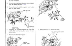
3. Remove the dashboard lower panel, knee bolster
pad, and knee bolster.
KNEE BOLSTER
KNEE BOLSTER
PAD
DASHBOARD
LOWER PANEL
4. Disconnect the connector between the cable reel
and the SRS main harness, then remove the con-
nector holder.
5. Remove the column lower panel.
COLUMN
LOWER PANEL
SRS MAIN HARNESS
(YELLOW)
CONNECTOR HOLDER
CABLE REEL
3-P CONNECTOR
(YELLOW)
6. Remove the column covers.
NOTE: Be careful not to damage the column covers.
UPPER COLUMN COVER
LOWER
COLUMN
COVER
7. Disconnect the TCS sensor connector.
TCS SENSOR CONNECTOR
(GREEN)
TCS SENSOR
Removal
CAUTION:
All SRS electrical wiring harnesses are covered with
yellow outer insulation.
Before disconnecting any part of the SRS wire
harness, install the short connectors (see pages
24-10(’93-’96),23-323(’91-’92) and 24-11(’93-’96), 23-323(’91-’92).
Replace the entire effected SRS harness assembly if
it has an open circuit or damaged wiring.
1. Disconnect both the negative cable and positive ca-
ble from the battery.
2. Remove the airbag assembly and steering wheel
from the column (see page 17-8).
3. Remove the dashboard lower panel, knee bolster
pad, and knee bolster.
KNEE BOLSTER
KNEE BOLSTER
PAD
DASHBOARD
LOWER PANEL
4. Disconnect the connector between the cable reel
and the SRS main harness, then remove the con-
nector holder.
5. Remove the column lower panel.
COLUMN
LOWER PANEL
SRS MAIN HARNESS
(YELLOW)
CONNECTOR HOLDER
CABLE REEL
3-P CONNECTOR
(YELLOW)
6. Remove the column covers.
NOTE: Be careful not to damage the column covers.
UPPER COLUMN COVER
LOWER
COLUMN
COVER
7. Disconnect the TCS sensor connector.
TCS SENSOR CONNECTOR
(GREEN)
TCS SENSOR
8. Remove the combination switch assembly from the
column shaft.
NOTE: The combination switch can be removed
by disconnecting only the TCS sensor connector.
COMBINATION SWITCH
ASSEMBLY
COLUMN SHAFT
9. Remove the steering joint cover.
CLIP
CLAMPS
STEERING JOINT COVER
10. Remove the steering joint bolts and toothed lock
washers from the steering joint.
STEERING JOINT
TOOTHED
LOCK WASHERS
STEERING JOINT BOLTS
11. Disconnect the ignition switch connectors and
remove the column holder, then remove the steer-
ing column assembly by removing the 8 mm bolts
and flange nuts.
STEERING
COLUMN ASSEMBLY
COLUMN
HOLDER
8 mm BOLTS
8 mm FLANGE NUTS